background image


3. Insert a blank data cartridge (scratch cartridge). After a few minutes, the cartridge will unload, then load again. At the end of the self test, the drive will eject the 

cartridge. 

¡

Refer to the chart below to determine if the test was successful or if it failed. 


4. Remove the cartridge from the drive and resume normal operations or refer to 

General Guidelines

 for help in resolving the error.  

Executing Service Function 2: Force dump 


1. Ensure there is no cartridge in the drive. 

Note:


If a cartridge is loaded in the drive, depression of the Unload button is interpreted as an unload request and the drive will ignore the second and third 
depressions. The drive cannot be put into Service mode while a cartridge is loaded.  

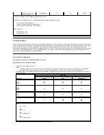
2. Press and hold the Unload button until the Ready LED begins flashing rapidly indicating Service Mode 1 has been accessed. The status LEDs will be in one of 

the following states.  

Important

The drive will timeout if the next step is not performed within 15 seconds. 

LED icon 

LED state 

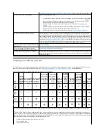
Test successful 

Test successful; drive 

needs cleaning 

Incorrect media 

Media failure 

Drive failure 


Note:  

l

If the Fault light is OFF after the test, the test was successful. If the Fault light is ON after the test, the test failed.  

l

The Clean LED may be OFF or ON after the test, depending on whether or not the drive needs cleaning.  

Key:


 = OFF  

 = ON  

 = Flashing slowly  


NOTE: The self test may be aborted before it has completed by pressing the Unload button. The drive will rewind the test cartridge, if necessary, unload it, 
and exit service mode.  

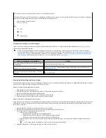
LED icon 

LED state 

Service Function 1; no drive dump 

in memory 

Service Function 1; drive dump in 

RAM 

Service Function 1; drive dump in 

flash memory 


Содержание PowerVault LTO-3-060

Страница 1: ...atory approvals and certifications is provided by the supplier and has not been independently verified or tested by Dell Dell cannot be responsible for damage caused as a result of either following or failing to follow these instructions All statements or claims regarding the properties capabilities speeds or qualifications of the part referenced in this document are made by the supplier and not b...

Страница 2: ...aximum speed at which data is transferred byte A string that consists of a certain number of bits usually 8 which are treated as a unit and represent a character A byte is a fundamental unit of data C C See Celsius capacity The amount of data that can be contained on storage media and expressed in bytes cartridge See tape cartridge cartridge door On a tape cartridge the hinged barrier that can be ...

Страница 3: ...ive head The component that records an electrical signal onto magnetic tape or reads a signal from tape into an electrical signal drive sense data See SCSI drive sense data dump See drive dump E eject To remove or force out from within enclosure A device such as a desktop unit tape cartridge autoloader or tape library into which you can install the tape drive error log Maintained by the tape drive...

Страница 4: ...that fits over a pair of protruding pins in a connector A jumper can be moved to change electrical connectors When in place the jumper connects the pins electrically 2 To place a jumper on a connector pin L label A slip of paper with an adhesive backing that can be written on and affixed to a tape cartridge as a means of identification or description label area On the LTO Ultrium Tape Cartridge a ...

Страница 5: ... its winding of one abamper per 4 pi centimeters of axial length offline The operating condition that the tape drive is in when the server s applications cannot interact with it online The operating condition that the tape drive is in when the server s applications can interact with it Open Systems Computer systems whose standards are not proprietary operating environment The temperature relative ...

Страница 6: ...tes which contains that information and which is sent back to the server by the drive Log sense data is used to diagnose problems especially if the problems are intermittent second One sixtieth of a minute sense data Data that describes an I O error Sense data is presented to a server in response to a Sense I O command server A functional unit that provides services to one or more clients over a n...

Страница 7: ...ectly read from and write to tape transfer rate See data transfer rate U Ultra160 LVD SCSI interface See Small Computer Systems Interface unload The act performed by the drive of unthreading tape from the drive s internal tape path and returning it with the leader block to the tape cartridge utility See utility program utility program A computer program that supports computer processes For example...

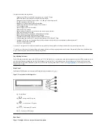
Страница 8: ...erVault LTO3 060 tape drive is a half high version of the Dell PowerVault 110T LTO 3 Tape Drive The LTO3 060 tape drive offers a formatted cartridge capacity of up to 400 GB 800 GB assuming 2 1 compression ratio and a data transfer rate of 60 MB per second Figure 1 shows the Dell PowerVault LTO3 060 tape drive Figure 1 Dell PowerVault LTO3 060 tape drive SCSI Bus Interface These tape drives are de...

Страница 9: ...tion l New service mode operations Assumes 2 1 compression The capacity and transfer rate you realize in practice depends on the data set which affects the actual compression ratio If the drive is in the process of writing host data to the cartridge the drive will stop accepting data from the host and will automaticllly flush write all buffered data to tape After cooling down the drive can resume ...

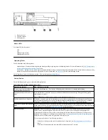
Страница 10: ... does not accept commands from the server Scroll through the Service Functions While in Service mode press the Unload button once per second to increment the Service Functions by one When you reach the desired Service Functions select it by either inserting a cartridge into the drive Service Function 1 or double clicking the Unload button Service Functions 2 4 and 5 See Table 1 Service Mode for mo...

Страница 11: ...le power as this will erase the contents of the dump LED icon Power on LED Test Power on Self Test POST in progress A cartridge is not loaded A cartridge is not loaded drive needs cleaning Cartridge loaded no activity Cartridge loaded no activity drive needs cleaning Data cartridge loaded activity Data cartridge loaded activity drive needs cleaning Cleaning cartridge loaded activity Cartridge is l...

Страница 12: ...ally Mounting Hardware Most systems use trays or rails to mount the tape drive For some systems no tray or rails are required Devices simply slide into the system s chassis and are fixed with screws Installing the Drive Step By Step Instructions Step 1 Unpacking the Drive Unpack the tape drive and store the packaging You may need the packaging if you return the unit for service A period of time is...

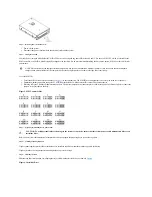
Страница 13: ...se a pair of needle nose pliers to connect the jumpers to the pins that are shaded Figure 5 SCSI Connector Pins Step 4 Preparing the Mounting Bay in Your System Refer to your system s documentation for instructions on how to prepare the mounting bay to receive the tape drive Step 5 Attaching Mounting Hardware If your system requires special rails or other hardware to install the tape drive mount t...

Страница 14: ...is point because you may have to move the drive to get the cables in place Step 7 Attaching Power and SCSI Cables Attach a spare power cable from the system s internal power supply to the power connector as shown in Figure 8 number 1 Attach a spare SCSI cable on the system s SCSI ribbon cable to the SCSI connector as shown on Figure 8 number 2 Figure 8 Attach Power and SCSI Cables NOTE If the driv...

Страница 15: ... click Manage then click Device Manager The tape drive should be listed under the Other Devices item as IBM Ultrium HH3 SCSI Sequential Device 4 Right click the IBM Ultrium HH3 SCSI Sequential Device listing click Uninstall and then click OK to confirm that you want to remove the device 5 Click Action in the upper left corner of the Computer Management dialog box 6 Click Scan for Hardware Changes ...

Страница 16: ...serted the support CD and click the Next button Driver names are as follows 1 Windows 2003 32 bit d Drivers Windows 2000 2003 32bit x86 dtapeW32 inf 2 Windows 2003 x64 d Drivers Windows 2003 x64 dtapex64 inf 14 You may have to click Continue to bypass a warning 15 Click Finish 16 Close the Device Properties dialog box 17 The drive now appears in Device Manager under Tape Drives and is ready to use...

Страница 17: ...pe Drive User s Guide See the User s Operating Guide supplied with your Tape Backup application For the latest supported software versions go to support dell com or visit the support site of your backup software vendor Please read all restrictions and disclaimers Back to Contents Page ...

Страница 18: ...olerance 5 VDC and 12 VDC 10 Current for 5 VDC 1 3 A minimum 2 8 A maximum Current for 12 VDC 0 2 A minimum 1 1 A maximum Typical Power Usage Idle mode with no cartridge 10 0 W Idle mode with a cartridge loaded 12 0 W Reading and writing at 4 10 m s 23 5 W Performance Interface Ultra160 LVD SCSI Recording format LTO Ultrium Generation 3 Media LTO Ultrium Capacity 400 GB native 800 GB compressed as...

Страница 19: ...de the ready LED is flashing rapidly indicating that the drive is ready to execute service function 1 Press the button once per second to increment the service functions one by one When you reach the desired service function execute it by either loading a cartridge or by double clicking the Unload button quickly Exact instructions for executing the service functions are given in Executing Service ...

Страница 20: ...te run time Less than 5 minutes 1 Ensure there is no cartridge in the drive Note If a cartridge is loaded in the drive depression of the Unload button is interpreted as an unload request and the drive will ignore the second and third depressions The drive cannot be put into Service mode while a cartridge is loaded The test can be aborted by pressing the eject button 2 Press and hold the Unload but...

Страница 21: ...Unload button until the Ready LED begins flashing rapidly indicating Service Mode 1 has been accessed The status LEDs will be in one of the following states Important The drive will timeout if the next step is not performed within 15 seconds LED icon LED state Test successful Test successful drive needs cleaning Incorrect media Media failure Drive failure Note l If the Fault light is OFF after the...

Страница 22: ...d service mode 6 To verify that the dump is in RAM complete the following steps a Ensure there is no cartridge in the drive Note If a cartridge is loaded in the drive the Unload button is interpreted as an unload request and the drive will ignore the second and third depressions The drive cannot be put into Service mode while a cartridge is loaded b Press and hold the Unload button until the Ready...

Страница 23: ... into Service mode while a cartridge is loaded 2 Press and hold the Unload button until the Ready LED begins flashing rapidly indicating Service Function 1 has been accessed The status LEDs will be in one of the following states 3 Press the Unload button 3 times to access Service Function 4 The status LEDs will be in one of the following states Key OFF Flashing slowly Flashing rapidly LED icon LED...

Страница 24: ...ns The drive cannot be put into Service mode while a cartridge is loaded b Press and hold the Unload button until the Ready LED begins flashing rapidly indicating Service Function 1 has been accessed The status LEDs will be in the following states c Verify that the Fault LED is solid ON n If the Fault LED is solid ON then the dump is in flash memory n If the Fault LED is not solid ON repeat the Se...

Страница 25: ... The status LEDs will be in one of the following states 3 Press the Unload button 4 times to access Service Function 5 The status LEDs will be in one of the following states LED icon LED state Service Function 1 no drive dump in memory Service Function 1 drive dump in RAM Service Function 1 drive dump in flash memory Key OFF ON Flashing slowly Flashing rapidly Important The drive will timeout if t...

Страница 26: ...hods of Receiving Errors and Messages The condition of the status light can also give information about the nature of the problem Refer to Interpreting error conditions using Status LEDs Error Conditions for more information Table 2 General Troubleshooting LED icon Service Function 1 with no dump Service Function 1 dump in RAM Key OFF Flashing slowly Flashing rapidly If the problem is this Do this...

Страница 27: ...urn it back on This will start the same sequence as a reset Follow the same process as the reset If the cartridge still will not eject contact your customer support resource SCSI log sense data such as TapeAlert flags at the server console See TapeAlert flags The server reported SCSI problems such as selection or command time outs or parity errors See Resolving Problems Reported by the System The ...

Страница 28: ...nator and retry the failing operation n Replace the SCSI cable and interposers if any and retry the failing operation n If these measures do not correct the problem contact Dell technical support If the error does not occur connect one tape drive at a time back to the bus and repeat step 3 for each tape drive until you can identify which drive is defective 4 Determine if the problem is with only o...

Страница 29: ...aused the error after each replacement Resolving Media Related Problems The tape drive has the capability to determine if a cartridge is faulty A faulty cartridge will be reported as a TapeAlert flag see TapeAlert Flags and the clean LED will flash slowly 2 Hz rate l If the operation in the other drive fails replace the media l If the operation succeeds see Executing Service Function 1 Standalone ...

Страница 30: ...tridge s write protect switch is set so that the tape drive can write data to the tape Setting the Write Protect Switch section 10 0Ah No removal Set when the tape drive receives an UNLOAD command after the system prevented the tape cartridge from being removed Refer to the documentation for your system s operating system 11 0Bh Cleaning media Set when you load a cleaning cartridge into the drive ...

Страница 31: ... indicates that the drive s temperature is exceeding the recommended temperature of the system see Specifications See General Guidelines in the troubleshooting section of this manual 37 25h Drive voltage Set when the drive detects that the externally supplied voltages are either approaching the specified voltage limits or are outside the voltage limits see Specifications See Step 7 Attaching Power...

Страница 32: ......

Страница 33: ... cartridge push the Unload button one more time Figure 10 Half high Drive Loading Unloading and Write Protecting Cartridges Only use LTO Ultrium format cartridges with your drive as specified in the LTO Ultrium standard Ensure that only one label is stuck to the label area of the cartridge Never use nonstandard labels and never stick anything to the cartridge other than in the label area The tape ...

Страница 34: ...ll rewind to the beginning and position itself ready for use Figure 12 Loading Unloading a Tape Cartridge 1 Ensure that the tape drive is powered on the Ready light is solid green 2 Press the eject button see number 1 in Figure 2 The drive rewinds the tape and partially ejects the cartridge The Activity light flashes green while the tape rewinds then goes out before the cartridge partially ejects ...

Страница 35: ...ipping envelope Always place it in a box or package l If you ship the cartridge in a cardboard box or a box of a sturdy material ensure the following Place the cartridge in polyethylene plastic wrap or bags to protect it from dust moisture and other contaminants Pack the cartridge snugly do not allow it to move around Double box the cartridge place it inside a box then place that box inside the sh...

Страница 36: ...g makes the tape unusable Cleaning the Tape Mechanism Dell PowerVault LTO3 060 drives have been developed to have a minimal cleaning requirement The clean LED will be lit solid when the drive needs cleaning Only insert a cleaning cartridge into the tape drive when the clean LED is lit An LTO Ultrium universal cleaning cartridge is supplied with each tape drive Do not use swabs or other means of cl...

Отзывы: