background image

Back to Contents Page

System Overview

Dell™ PowerVault™ 715N Systems Service Manual

Overview

Power Protection Devices

System Features

Other Documents You Might Need

Service Features

Technical Specifications

Overview

Your network attached storage (NAS) appliance enables you to easily add storage to a workgroup, small office,

or small business network and offload the file management responsibilities from the server. The NAS appliance

is a "headless" device, which means it has no keyboard, mouse, or monitor, but can be managed through the

network or by using console redirection through a serial connection. The system offers the data security

capabilities of general-purpose servers. 

This document provides basic information about the system features, service features, and specifications. 

System Features

The system offers the following major features:

An Intel® Celeron

 microprocessor with an internal bus speed of at least 850 MHz or an Intel Pentium® III

microprocessor with an internal bus speed of at least 1 GHz

1-U chassis

Two DIMM slots

Four IDE hard drives connected to four IDE master channels in a software RAID configuration

162-W power supply

System cooling fan and two power-supply cooling fans

Serial port used for console redirection

One 32-bit, 33-MHz low-profile PCI slot

A minimum of 256 MB (for early systems with a SN1A system board) or 384 MB (for later systems with a SN1B

system board) of SDRAM system memory, upgradable by installing registered PC-133 SDRAM memory modules in

the two memory module sockets

A flash BIOS that can be upgraded through console redirection

Two integrated Intel 82559 10/100+ NICs with RJ-45 Ethernet connectors


The following software is included in the system:

Microsoft® Windows® Powered operating system with Service Pack 2.

Microsoft Server Appliance (SA) kit.

Services for UNIX®, Novell® NetWare®, and Macintosh (integrated into the Microsoft Windows Powered operating

system).

Protocol support for TCP/IP, DHCP (client support), DNS (client support), NIS (client support), IPX, CIFS, NFS, and

IPV6.

First Time Configuration support through DHCP, Dell OpenManage™ Kick-Start, or RAS serial connection (setup

through serial connection in non-DHCP environments).

Содержание PowerVault 715N

Страница 1: ...n any manner whatsoever without the written permission of Dell Computer Corporation is strictly forbidden Trademarks used in this text Dell PowerVault Dell ActiveArchive and Dell OpenManage are trademarks of Dell Computer Corporation Microsoft Windows and Windows NT are registered trademarks of Microsoft Corporation Intel and Pentium are registered trademarks and Celeron is a trademark of Intel Co...

Страница 2: ...peed of at least 1 GHz 1 U chassis Two DIMM slots Four IDE hard drives connected to four IDE master channels in a software RAID configuration 162 W power supply System cooling fan and two power supply cooling fans Serial port used for console redirection One 32 bit 33 MHz low profile PCI slot A minimum of 256 MB for early systems with a SN1A system board or 384 MB for later systems with a SN1B sys...

Страница 3: ... in a variety of types and usually provide a level of protection commensurate with the cost of the device Surge protectors prevent voltage spikes such as those caused during an electrical storm from entering a system through the electrical outlet Surge protectors however do not offer protection against brownouts which occur when the voltage drops more than 20 percent below the normal AC line volta...

Страница 4: ...rately from the system This documentation includes information that you need to configure and install these options in your system Technical information files sometimes called readme or release notes files that might be installed on the CDs that came with your system to provide last minute updates about technical changes to the system or advanced technical reference material intended for experienc...

Страница 5: ... Ethernet controllers Power Wattage one 162 W power supply Input voltage 100 to 240 V at 47 63 Hz autoranging Output voltages and maximum current 5 VDC at 15 A 3 3 VDC at 8 A 12 VDC at 8 A 12 VDC at 0 1 A 5 Vfp volts flea power at 1 A Backup battery CR2032 3 V lithium coin cell Physical Height 4 2 cm 1 6 inches Width 42 5 cm 16 7 inches Depth 46 3 cm 18 2 inches Weight 9 5 kg 21 lb maximum configu...

Страница 6: ... zero to peak at a sweep of 3 to 200 Hz at 0 5 octave per minute Maximum shock Operating half sine wave 31 G bottom only tested with pulse duration of 2 6 ms or less 20 inches s 51 cm s Storage non operating half sine wave 71 G all six sides tested with pulse duration of 2 ms or less 35 inches s 89 cm s Altitude Operating 15 2 to 3 048 m 50 to 10 000 ft Storage 15 2 to 10 668 m 50 to 35 000 ft Bac...

Страница 7: ...form the following steps 1 Ask the user to back up any data on the hard drive if the system s condition permits See the documentation provided with the operating system or applications software for information about backing up data 2 Ask the user to duplicate the problem by repeating the operations he or she was performing at the time the problem occurred Can the user duplicate the problem Yes Pro...

Страница 8: ...ping or grinding sound when you access a hard drive See Hard Drives in Removing and Replacing Parts Internal Visual Inspection NOTICE Before you proceed with the internal visual inspection described in this section ensure that the user has saved all open files and exited all open application programs if possible to prevent loss of data A simple visual inspection of a system s interior hardware can...

Страница 9: ...5200 for the bits per second 8 for data bits None for parity 1 for stop bits and Xon Xoff for flow control 3 Restart the appliance 4 Press F2 immediately after you see the following message Press F2 to Enter the Function Select Menu NOTE If you use a version of Microsoft Windows 2000 earlier than Service Pack 2 the function keys do not work You must press Esc 2 If you wait too long and your operat...

Страница 10: ...Back to Contents Page ...

Страница 11: ...o the appliance and enter the BIOS Setup utility 2 Select Advanced CMOS Setup 3 Select View DMI Event and then press Enter Table 1 lists the system error messages and the probable cause for each message NOTE If you receive a system message that is not listed in Table 1 check the documentation for the application program that is running when the message appears or the operating system documentation...

Страница 12: ...y looking up the meaning of the beep code use the system diagnostics to identify a more serious cause See Running System Diagnostics Table 2 System Beep Codes Code Cause Corrective Action 1 The memory refresh circuitry on the system board is faulty Replace the system and midplane board 2 Base 64 KB memory failure Switch memory modules Remove and reseat the memory modules If the problem persists re...

Страница 13: ...to the network through the LAN 2 port Flashing green indicates that activity between the system and other devices on the network Off indicates that the system is disconnected from the network or that the LAN 2 port is not working properly Hard Drive Indicators Each hard drive has two LED indicators an operation LED on the left side and an activity LED on the right side LEDs are visible when the be...

Страница 14: ...cument This section provides servicing procedures for components inside the system Before you start any of the procedures in this section perform the following tasks Perform the procedures described in External Visual Inspection Read the safety information in the System Information booklet When a replacement procedure is not provided use the removal procedure in reverse order to install the replac...

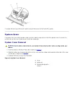
Страница 15: ...onents System Cover Removal CAUTION See the safety instructions in your System Information booklet before working inside your system 1 Push the latches on the top of the system inward see Figure 2 2 Slide the system cover backward about 16 mm 0 6 inch until the embossed arrowheads on the sides of the cover and chassis are aligned see Figure 2 3 Carefully lift the cover away from the system Figure ...

Страница 16: ...moved to provide an interior view of the system Refer to this illustration to locate interior features and components discussed later in this manual Figure 3 Inside the System 1 Hard drives 4 2 Midplane board 3 Cooling fan assembly 4 Power supply 5 Microprocessor and heat sink 6 System board 7 Memory modules 2 8 PCI riser card The system board holds the system s control circuitry and other electro...

Страница 17: ...ead the safety instructions in your System Information document 1 Shut down the system and disconnect the power cables from their outlets 2 Remove the bezel 3 Remove the power cord from the system power input receptacle 4 Open the drive carrier handle by pushing the release lever to the right see Figure 4 5 Pull open the latch and use it to pull the drive carrier out of the drive bay see Figure 4 ...

Страница 18: ...ive and carrier into its slot in the drive bay see Figure 4 6 Close the handle until it engages the front panel locking the drive in place 7 Replace the bezel 8 Run the system diagnostics to test and prepare the new drive 9 Follow the appropriate procedure for restoring your data and adding mirrors in the section Managing Hard Drives in the System Administrator s Guide Control Panel Board In Figur...

Страница 19: ...ooling Fan A single fan assembly is mounted beside the microprocessor and heat sink socket This cooling fan directs cooling air across the microprocessor and heat sink and across the memory modules and the PCI expansion card before exiting the chassis through holes in the back panel CAUTION Read the safety instructions in your System Information document Removing the Fan Assembly If you observe th...

Страница 20: ...s on the front of the midplane board connect to the four hard drives On the back of the midplane board is a single large connector that connects to the system board providing control and data signals and power for the four hard drives see Figure 8 A ribbon cable from the midplane board connects to the control panel board CAUTION Read the safety instructions in your System Information document Figu...

Страница 21: ...ane board toward the front of the system chassis about 6 3 mm 0 25 inch 16 Carefully pivot the system board and midplane board up and out of the chassis Be sure to lift the midplane board first and when it is free of the chassis pull the system board away from the back panel 17 Place the system board and midplane board on a smooth antistatic surface 18 Remove the microprocessor 19 Remove the memor...

Страница 22: ... board or components that attach to the system board Figure 9 System Board Features 1 Fan power connector CPUFAN1 2 DIP switch SW3 3 Microprocessor and heat sink CPU 4 Power supply connectors CN1 and CN2 5 Serial port connector COM1 6 Memory modules DIMM1 and DIMM2 7 PCI riser card slot PCI1 8 LAN connectors LAN1 and LAN2 9 Battery connector BT1 10 Clear CMOS jumper JP1 11 System version jumper JP...

Страница 23: ...system board see Figure 9 6 Using a 1 Phillips screwdriver remove the four Phillips screws securing the power supply to the back of the system chassis 7 Push the power supply forward and away from the back panel about 6 3 mm 0 25 inch The power supply must clear the locking tab on the floor of the chassis 8 Lift the power supply out of the chassis Expansion Card The system has a single PCI expansi...

Страница 24: ...alling a filler bracket over an empty expansion slot is necessary to maintain Federal Communications Commission FCC certification of the system The brackets also keep dust and dirt out of the system and aid in proper cooling and airflow inside the system 7 Replace the system cover 8 Reconnect the system and peripherals to the power source and then turn on the system Expansion Card Replacement To i...

Страница 25: ...f the system chassis see Figure 12 CAUTION Read the safety instructions in your System Information document Riser Card Removal 1 Turn off the system including any attached peripherals and disconnect the system from its electrical outlet 2 Remove the system cover 3 Remove the expansion card 4 Grasp the riser card on each end and lift it out of its slot on the system board Use care to lift it out ev...

Страница 26: ...istrator s Guide for information about connecting to the system through console redirection Table 1 illustrates two sample memory configurations based on these guidelines Table 1 Sample DIMM Configurations Desired Memory DIMM1 DIMM2 256 MB 256 MB Open 512 MB 512 MB Open Performing a Memory Upgrade CAUTION Before you perform this procedure you must turn off the system and disconnect it from its pow...

Страница 27: ...xtd Memory setting to reflect the newly installed memory 8 If the Extd Memory value is incorrect one or more of the memory modules might not be installed properly Repeat steps 2 5 ensuring that the memory modules are firmly seated in their sockets 9 Run the system memory test in the system diagnostics 10 Replace the system cover Installing Memory Modules CAUTION Before you perform this procedure y...

Страница 28: ...nstall the remaining memory modules 9 Perform steps 5 10 of the procedure Performing a Memory Upgrade Removing Memory Modules CAUTION Before you perform this procedure you must turn off the system and disconnect it from its power source For more information see the safety instructions in your System Information document CAUTION See Protecting Against Electrostatic Discharge in the safety instructi...

Страница 29: ...e it from the retaining tab on the ZIF socket see Figure 15 4 Remove the securing clip 5 Carefully remove the heat sink and set it down with the underside of the heat sink facing up CAUTION Ensure that the thermal pad on the underside of the heat sink is not damaged during handling NOTE Observe the orientation of the heat sink with respect to the microprocessor and its ZIF socket 6 Pull the socket...

Страница 30: ...he microprocessor is fully seated in the socket rotate the socket release lever back down until it snaps into place securing the microprocessor 12 Place the heat sink you removed in step 5 on top of the microprocessor see Figure 15 CAUTION Ensure that the thermal pad on the underside of the heat sink is not damaged during handling 13 Orient the securing clip as shown in Figure 15 14 Hook the end o...

Страница 31: ...M may lose its system configuration information This situation is not caused by a defective battery You can operate the system without a battery however the system configuration information maintained by the battery in NVRAM is erased each time you shut down the system Therefore you must re enter the system configuration information and reset the options each time the system initializes until you ...

Страница 32: ...ttings Also re enter any system configuration information that is no longer displayed on the BIOS Setup screens and then exit the BIOS Setup utility 10 To test the newly installed battery shut down and disconnect the system from the electrical source for at least an hour 11 After an hour connect the system to an electrical source and turn on the power 12 Enter the BIOS Setup utility and if the tim...

Страница 33: ...ully fit it down onto the pin s indicated Figure 1 Jumpers NOTICE Make sure the system is turned off before you change a jumper setting Otherwise damage to the system or unpredictable results might occur A jumper is referred to as open or unjumpered when the plug is pushed down over only one pin or if there is no plug at all When the plug is pushed down over two pins the jumper is referred to as j...

Страница 34: ... a system version number of SN1A have the JP5 jumper set on pins 1 and 2 Later systems with a system version number of SN1B have the JP5 jumper set on pins 2 and 3 Do not change these jumper settings NOTICE All DIP switch SW3 positions must remain in the OFF position Do not change these DIP switch settings Figure 3 System Board Jumpers 1 System version jumper JP5 2 Clear CMOS jumper JP1 3 Battery ...

Страница 35: ...4 System Board Features 1 Fan power connector CPUFAN1 2 DIP switch SW3 3 Microprocessor and heat sink CPU 4 Power supply connectors CN1 and CN2 5 Serial port connector COM1 6 Memory modules DIMM1 and DIMM2 7 PCI riser card slot PCI1 8 LAN connectors LAN1 and LAN2 9 Battery connector BT1 10 Clear CMOS jumper JP1 11 System version jumper JP5 Back to Contents Page ...
Страница 36: ...uration information and optional settings Print or record the information for future reference Entering the BIOS Setup Utility 1 Using a null modem serial cable connect the client system to the NAS system 2 Turn on the client system and set up a Hyperterminal connection a Click the Start button and point to Programs Accessories Hyperterminal Hyperterminal b Select 115200 for the bits per second 8 ...

Страница 37: ...in the help area the changes take effect immediately Table 2 shows a list of keystroke combinations that you must use with versions of Windows 2000 released prior to Service Pack 2 Table 2 Console Redirection Keys Normal Keys Keys Used for Windows 2000 Prior to Service Pack 2 and Windows XP Keys Used for All Other Windows Operating Systems Home Esc h Esc h End Esc k Esc k Insert Esc Esc Delete Esc...

Страница 38: ...it Without Saving Exits the BIOS Setup utility and does not save any changes you made Standard CMOS Setup Screen Use this screen to view and set basic information such as date time and primary or secondary drives Date and Time Sets the correct date and time for the system Primary Secondary Master Slave Displays the characteristics of IDE 0 and IDE 1 which are the first two drives of the system The...

Страница 39: ...transaction cycles Peripheral Setup Use this screen to set parameters for peripheral items on the system Onboard Serial Port 1 and Serial Port 2 Disables the serial ports or assigns a port address and name to the ports Dell recommends that you set the items to Auto so the system can dynamically assign port addresses and names Onboard IDE Enables or disables the primary and secondary IDE channels i...

Страница 40: ...and then transferring the BIOS file to the NAS system Downloading and Copying BIOS to the NAS System To update the BIOS you must be logged into the NAS Manager as an administrator You can log in only if the NAS system is on the network or if the client system is connected directly to the NAS system with a serial cable see the User s Guide for complete instructions in setting up a HyperTerminal con...

Страница 41: ...tag For example if your service tag number is 1234567 you would enter https DELL1234567 1279 Port 1279 uses secured socket layers SSL to encrypt data going to and coming from the NAS system to provide data security NOTICE Although port 1278 can be used it uses plain text authentication which can be a significant security risk Therefore using port 1278 is not recommended 3 When the Enter Network Pa...

Страница 42: ...S from support dell com 2 Using a null modem serial cable connect the client system to the NAS system 3 Turn on the client system and set up a Hyperterminal connection a Click the Start button and point to Programs Accessories Hyperterminal Hyperterminal b In the program group double click Hyperterminal c Select 115200 for the bits per second 8 for data bits None for parity 1 for stop bits and Xon...

Страница 43: ...ers are located next to the battery with jumper 1 the closest to the battery and jumper 3 the farthest from the battery 4 Move the jumper plug back to jumpers 1 2 5 Replace the battery and system cover 6 Reconnect the system to an electrical outlet and to the client system 7 Turn on the system The system beeps twice to indicate that the password has been cleared 8 If you want enter a new superviso...

Страница 44: ...an error message appears on your monitor screen while the system boots make a note of the message Then before entering the BIOS Setup utility see System Beep Codes and System Messages in Codes Error Messages and Indicators for an explanation of the message and suggestions for correcting any errors NOTE It is normal to receive an error message the first time you boot your system after installing a ...

Отзывы: