


lists the drive indicator patterns for RAID hard drives. Different patterns are displayed as drive events occur in the system. For example, if a hard
drive fails, the "drive failed" pattern appears. After the drive is selected for removal, the "drive being prepared for removal" pattern appears, followed by the
"drive ready for insertion or removal" pattern. After the replacement drive is installed, the "drive being prepared for operation" pattern appears, followed by
the "drive online" pattern.
Table 1-3. Hard-
Drive Indicator Patterns for RAID
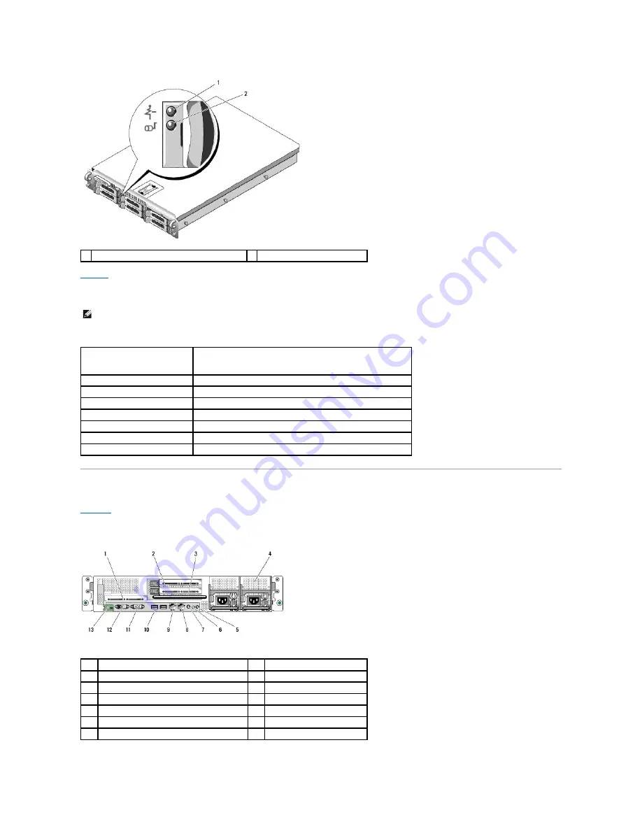
Back-Panel Features and Indicators
shows the controls, indicators, and connectors located on the system's back panel.
Figure 1-3. Back-Panel Features and Indicators
1 drive-status indicator (green and amber)
2 green drive-activity indicator
NOTE:
For non-RAID configurations, only the drive-
activity indicator is active. The drive
-status indicator is off.
Condition
Drive-Status Indicator Pattern
Identify drive/preparing for removal Blinks green two times per second
Drive ready for insertion or removal Off
Drive predicted failure
Blinks green, amber, and off.
Drive failed
Blinks amber four times per second.
Drive rebuilding
Blinks green slowly.
Drive online
Steady green.
Rebuild aborted
Blinks green three seconds, amber three seconds, and off six seconds.
1
center PCI riser (slot 1)
2
left PCI riser (slot 2)
3
left PCI riser (slot 3)
4
power supplies (2)
5
system identification button
6
system status indicator
7
system status indicator connector
8
NIC2 connector
9
NIC1 connector
10
USB connectors (2)
11
video connector
12
serial connector
13
remote access controller (optional)


