the processor. Do not pry the heat sink off of the processor.
6.
Lift the heat sink off of the processor and set the heat sink upside down so as not to contaminate the thermal grease.
7.
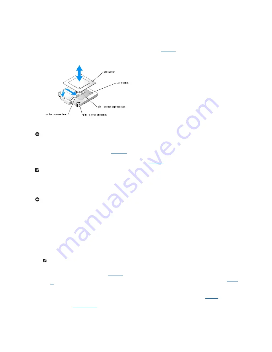
Pull the socket-release lever straight up until the processor is released from the socket. See
Figure 6
-12
.
Figure 6-12. Installing and Removing the Processor
8.
Lift the processor out of the socket and leave the release lever up so that the socket is ready for the new processor.
9.
Unpack the new processor.
If any of the pins on the processor appear bent, see "
Getting Help
."
10.
Align the pin-1 corner of the processor with the pin-1 corner of the ZIF socket. See
Figure 6
-12
.
Identify the pin-1 corner of the processor by locating the tiny gold triangle on one corner of the processor. Place this corner in the same corner of the ZIF
socket identified by a corresponding triangle.
11.
Install the processor in the socket.
a.
If the release lever on the processor socket is not positioned all the way up, move it to that position.
b.
With the pin-1 corners of the processor and socket aligned, set the processor lightly in the socket, making sure all pins are matched with the
correct holes in the socket.
Because the system uses a ZIF processor socket, do not use force, which could bend the pins if the processor is misaligned.
When the processor is positioned correctly, it drops down into the socket with minimal pressure.
c.
When the processor is fully seated in the socket, rotate the socket release lever back down until it snaps into place, securing the processor.
12.
Install the heat sink.
a.
Using a clean lint-free cloth, remove the existing thermal grease from the heat sink.
b.
Apply thermal grease evenly to the top of the processor.
c.
Place the heat sink onto the processor. See
Figure 6
-10
.
d.
Using a #2 Phillips screwdriver, tighten in a diagonal pattern the four captive screws that secure the heat sink to the system board. See
Figure 6
-
11
.
e.
Repeat for the other heat sink.
13.
Install the processor cooling shroud by aligning the arrows on the shroud with the arrows on the chassis next to the fans. See
Figure 6
-9
.
14.
Close the system. See "
Closing the System
" in "Troubleshooting Your System."
As the system boots, it detects the presence of the new processor and automatically changes the system configuration information in the System Setup
program.
NOTICE:
Be careful not to bend any of the pins when removing the processor. Bending the pins can permanently damage the processor.
NOTE:
Identifying the pin-1 corners is critical to positioning the processor correctly.
NOTICE:
If you position the processor incorrectly, you can permanently damage the processor and the system when you turn it on. When placing the
processor in the socket, make sure that all of the pins on the processor enter the corresponding holes. Be careful not to bend the pins.
NOTE:
Use the heat sink that you removed earlier in this procedure.
Содержание PowerEdge SC1425
Страница 27: ...Back to Contents Page ...


