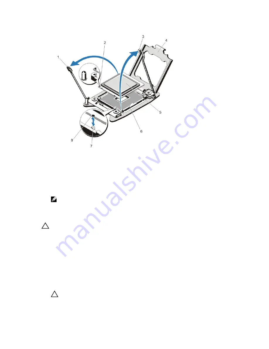
Figure 46. Removing and Installing a Processor
1.
processor socket-release lever
2.
pin 1 indicator
3.
processor socket-release lever
4.
processor shield
5.
processor
6.
ZIF socket
7.
socket keys (4)
8.
notches in processor (4)
NOTE: After removing the processor, place it in an antistatic container for reuse, return, or temporary storage.
Do not touch the bottom of the processor. Touch only the side edges of the processor.
Installing The Processor
CAUTION: Many repairs may only be done by a certified service technician. You should only perform
troubleshooting and simple repairs as authorized in your product documentation, or as directed by the online or
telephone service and support team. Damage due to servicing that is not authorized by Dell is not covered by your
warranty. Read and follow the safety instructions that came with the product.
1.
Turn off the system, including any attached peripherals, and disconnect the system from the electrical outlet. When
disconnected from the power source, press and hold the power button for three seconds to fully drain the system
of stored power prior to removing the cover.
2.
Open the system.
3.
Remove either the cooling shroud or the processor expansion module, as applicable.
4.
Unpack the new processor.
5.
Align the processor with the socket keys on the ZIF socket.
CAUTION: Positioning the processor incorrectly can permanently damage the system board or the processor.
Be careful not to bend the pins in the socket.
81
Содержание PowerEdge R820
Страница 1: ...Dell PowerEdge R820 Owner s Manual Regulatory Model E21S Series Regulatory Type E21S001 ...
Страница 8: ...8 ...
Страница 32: ...32 ...
Страница 42: ...Figure 15 Memory Socket Locations on the System Board 42 ...
Страница 124: ...124 ...
Страница 142: ...142 ...


