Dell PowerEdge C6145 Скачать руководство пользователя страница 176


176

  |  

Installing System Components 


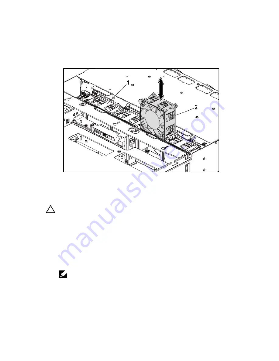
Figure 3-36.   Removing and Installing a Cooling Fan 


cooling-fan bracket 

cooling fans (4) 

Installing a Cooling Fan 


CAUTION: Many repairs may only be done by a certified service technician. You 
should only perform troubleshooting and simple repairs as authorized in your 
product documentation, or as directed by the online or telephone service and 
support team. Damage due to servicing that is not authorized by Dell is not 

covered by your warranty. Read and follow the safety instructions that came with 
the product. 

1


Align the cooling fan and slide it in the cooling-fan bracket until the 
cooling fan is firmly seated. See Figure 3-36. 


NOTE: The fan blades should face the front panel of the system. 

2


Connect the fan’s power cable to the connector on the fan-controller 
board. See Figure 3-48. 
You must route these cables properly through the tabs on the chassis to 
prevent them from being pinched or crimped. 

Содержание PowerEdge C6145

Страница 1: ...Regulatory Model B05S DellPowerEdgeC6145 Systems Hardware Owner s Manual ...

Страница 2: ... 2013 Dell Inc All rights reserved Reproduction of these materials in any manner whatsoever without the written permission of Dell Inc is strictly forbidden Trademarks used in this text Dell the DELL logo and PowerEdge are trademarks of Dell Inc AMD is a registered trademark of Advanced Micro Devices Inc Other trademarks and trade names may be used in this publication to refer to either the entiti...

Страница 3: ...s 20 Power and System Board Indicator Codes 22 Power Supply Indicator Codes 23 BMC Heart Beat LED 24 Post Error Code 25 Collecting System Event Log SEL for Investigation 25 Post Error Code Event 43 Other Information You May Need 44 Recovery Mode 45 2 Using the System Setup Program 46 Start Menu 46 System Setup Options at Boot 46 Console Redirection 47 Main Menu 49 Main Screen 49 BIOS Firmware 50 S...

Страница 4: ...orm Management Link 58 Memory Configuration 59 IDE Configuration 60 USB Configuration 64 PCI Configuration 65 Hyper Transport Configuration 69 I O Virtualization 70 Boot Menu 71 Boot Settings Configuration 72 Boot Device Priority 74 Hard Disk Drives 75 Removable Drives 76 CD DVD Drives 77 USB Drives 78 Network Drives 79 Security Menu 80 Server Menu 82 System Management 84 Remote Access Configurati...

Страница 5: ...k 106 Removing a Hard Drive Carrier 106 Installing a Hard Drive Carrier 107 Removing a Hard Drive From a Hard Drive Carrier 108 Installing a Hard Drive Into a Hard Drive Carrier 109 Power Supplies 110 Removing a Power Supply 113 Installing a Power Supply 114 System Board Assembly 115 Removing a System Board Assembly 115 Installing a System Board Assembly 116 Air Ducts 116 Removing the Air Duct 116...

Страница 6: ...nal 135 Removing the LSI 9260 8i RAID Battery 135 Installing the LSI 9260 8i RAID Battery 136 Removing the LSI 9260 8i RAID Battery Carrier 137 Installing the LSI 9260 8i RAID Battery Carrier 138 LSI 9265 8i Card 139 Removing the LSI 9265 8i Card 139 Installing the LSI 9265 8i Card 142 Cable Routing for LSI 9265 8i Card 143 LSI 9265 8i RAID Battery Optional 145 Removing the LSI 9265 8i RAID Batter...

Страница 7: ...the Mellanox Card 158 Installing the Mellanox Card 160 Mezzanine Card Bridge Board 161 Removing the Mezzanine Card Bridge Board 161 Installing the Mezzanine Card Bridge Board 162 System Memory 163 Supported DIMM Configuration 163 Removing the Memory Modules 166 Installing the Memory Modules 167 System Battery 169 Replacing the System Battery 169 System Board 171 Removing a System Board 171 Install...

Страница 8: ...oard 190 Cable Routing for Power Distribution Board 191 Fan Controller Board 192 Removing the Fan Controller Board 192 Installing the Fan Controller Board 193 Cable Routing for Fan Control Board 194 Expander Card Optional 195 Removing the Expander Card 195 Installing the Expander Card 199 Front Panels 200 Removing the Front Panel 200 Installing the Front Panel 203 Sensor Boards 204 Removing the Se...

Страница 9: ...Serial I O Device 214 Troubleshooting a NIC 215 Troubleshooting a Wet System 216 Troubleshooting a Damaged System 217 Troubleshooting the System Battery 217 Troubleshooting Power Supplies 218 Troubleshooting System Cooling Problems 219 Troubleshooting a Fan 220 Troubleshooting System Memory 220 Troubleshooting a Hard Drive 222 Troubleshooting a Storage Controller 223 Troubleshooting Expansion Card...

Страница 10: ...rs 236 SAS Mezzanine Card Connectors 237 10GbE Mezzanine Card Connectors 238 Fan Controller Board Connectors 239 Power Distribution Board Connectors 240 Sensor Board Connectors 241 Switch and Jumper Settings 242 System Configuration Switch Settings 242 3 5 Backplane With CPLD Jumper Settings 243 3 5 Backplane With Expander Jumper Settings 244 2 5 Backplane Expander Card Jumper Settings 245 6 Getti...

Страница 11: ...tup Options at Boot on page 46 F12 Starts Preboot eXecution Environment PXE boot Ctrl C Enters the SAS 2008 Daughter Card Configuration Utility For more information see the SAS adapter documentation Ctrl H Enters the LSI 9260 configuration utility For more information see the documentation for your SAS RAID card Ctrl S Enters the utility to configure NIC settings for PXE boot For more information ...

Страница 12: ...s Figure 1 1 Front Panel 3 5 x8 Hard Drives With Two Motherboards Figure 1 2 Front Panel 3 5 x12 Hard Drives With Two Motherboards Figure 1 3 Front Panel 3 5 x8 Hard Drives With One Motherboard Figure 1 4 Front Panel 3 5 x12 Hard Drives With One Motherboard ...

Страница 13: ...Your System 13 Figure 1 5 Front Panel 2 5 x18 Hard Drives With Two Motherboards Figure 1 6 Front Panel 2 5 x24 Hard Drives With Two Motherboards Figure 1 7 Front Panel 2 5 x24 Hard Drives With One Motherboard ...

Страница 14: ...turning off the system using the power button causes the system to perform a graceful shutdown before power to the system is turned off NOTE To force an ungraceful shutdown press and hold the power button for 5 seconds 2 4 System identification indicator button motherboards 1 2 The identification button can be used to locate a particular system and motherboard within a chassis When the button is p...

Страница 15: ...y Off Off Off Drive On line Access Blinking when active On Off Drive Failed Off Blinking when active Off On 150 ms Off 150 ms Drive Rebuilding Blinking when active On 400 ms Off 100 ms Off Drive Rebuilding Abort Off Blinking when active On 3000 ms Off 3000 ms Off 3000 ms Off 3000 ms Off 3000 ms Off 3000 ms On 3000 ms Off 3000 ms Predicted Failure SMART Off Blinking when active On 500 ms Off 500 ms...

Страница 16: ...led Off Blinking when active Off On 125 ms Off 125 ms Drive Rebuilding Blinking when active On 400 ms Off 100 ms Off Drive Rebuilding Abort Off Blinking when active On 3000 ms Off 3000 ms Off 3000 ms Off 3000 ms Off 3000 ms Off 3000 ms On 3000 ms Off 3000 ms Predicted Failure SMART Off Blinking when active On 500 ms Off 500 ms Off 1000 ms Off 500 ms On 500 ms Off 1000 ms Drive Identify Preparing f...

Страница 17: ...25 ms Off 125 ms Drive Rebuilding Blinking when active On 400 ms Off 100 ms Off Drive Rebuilding Abort Off Blinking when active On 3000 ms Off 3000 ms Off 3000 ms Off 3000 ms Off 3000 ms Off 3000 ms On 3000 ms Off 3000 ms Predicted Failure SMART Off Blinking when active On 500 ms Off 500 ms Off 1000 ms Off 500 ms On 500 ms Off 1000 ms Drive Identify Preparing for removal Blinking when active On 25...

Страница 18: ...dded 10 100 1000 NIC connectors 5 Serial port Connects a serial device to the system 6 VGA port Connects a VGA display to the system 7 System identification indicator Both the system management software and the identification buttons located on the front can cause the indicator to flash blue to identify a particular system and system board Lights amber when the system needs attention due to a prob...

Страница 19: ...em NOTE When powering on the system the video monitor can take from several seconds to over 2 minutes to display an image depending on the amount of memory installed in the system NOTE On ACPI compliant operating systems turning off the system using the power button causes the system to perform a graceful shutdown before power to the system is turned off NOTE To force an ungraceful shutdown press ...

Страница 20: ...speed Blinking green Port identification with 10 or 100 Mbps speed Solid amber Linking at 1 Gbps speed Blinking amber Port identification with 1 Gbps speed Off Linking at 10 Mbps speed when the link activity LED is green no link when the link activity LED is off NIC Status Indicator Link Activity Condition Solid green LAN linking No access Blinking green LAN accessing Off No link ...

Страница 21: ...link activity indicator NIC Status Indicator Speed Condition Green Linking at 100 Mbps speed Off Linking at 10 Mbps speed when the link activity LED is solid green no link when the link activity LED is off NIC Status Indicator Link Activity Condition Green LAN linking Accessing Off No link ...

Страница 22: ...sociated with the status codes Table 1 4 Status Indicator Codes Component Indicator Condition Power on indicator Green Solid Blinking Off Power On S0 S1 BMC critical condition event in Power On mode S0 S1 Power Off mode S4 S5 Amber Blinking Off BMC Critical condition event in Power On mode S0 S1 BMC Critical condition event in Power Off mode S4 S5 Power On S0 S1 Power Off S4 S5 System identificati...

Страница 23: ...r supply is on AC OK DC OK or in standby mode 100 VAC 120 VAC for 1023 W 200 VAC 240 VAC for 1100 W 200 VAC 240 VAC for 1400 W Solid yellow Power supply is at fault condition UVP OVP OCP SCP OTP Fan Fault Off Power supply is off or AC input voltage is out of normal operating range 100 VAC 120 VAC for 1023 W 200 VAC 240 VAC for 1100 W 200 VAC 240 VAC for 1400 W ...

Страница 24: ... provides BMC heart beat LED CR2 for BMC debugs The BMC heart beat LED is green When the system AC power is on this LED will light When BMC firmware is ready the BMC heart beat LED will blink Figure 1 14 BMC Heart Beat LED 1 BMC heart beat LED 2 system board ...

Страница 25: ...e message is displayed on the screen An error record is logged to the SEL The system will continue booting with a degraded state The user may want to replace the erroneous unit 2 Pause The message is displayed on the screen an error is logged to the SEL and user input is required to continue The user can take immediate corrective action or choose to continue booting 3 Halt The message is displayed...

Страница 26: ... Clear password by switch 004Ah ADM Module Error Unspecified Board repair 004Bh Language Module Error 7 Unspecified Board repair 005Dh S M A R T Command Failed S M A R T Status BAD Backup and Replace HDD ATAPI IDE device failure Change HDD 005Eh Password Check Failed Other preboot password violation Clear password by switch 0060h Primary Master Hard Disk Error HDD ATAPI IDE device failure Change H...

Страница 27: ...t Install same model CPU 4168h DIMM CRC Error or be ignore POST Error DIMM bad Change DIMM 4169h DIMM Chip Select Disable Test Fail DIMM bad Change DIMM 5120h CMOS cleared by jumper CMOS clear by jumper No action 5122h Password cleared by jumper Password clear by jumper No action 8104h Warning Port 60h 64h emulation is not supported by this USB Host Controller Not supported by the HC Board repair ...

Страница 28: ... Temp Temperature Upper Non Critical Going High Asserted Upper critical event asserted Processor 1 Temp Temperature Upper Critical Going High Asserted Upper non recoverable event asserted Processor 1 Temp Temperature Upper Non Recoverable Going High Asserted Upper non critical event deasserted Processor 1 Temp Temperature Upper Non Critical Going High Deasserted Upper critical event deasserted Pro...

Страница 29: ...ecoverable Going High Asserted Upper non critical event deasserted Processor 2 Temp Temperature Upper Non Critical Going High Deasserted Upper critical event deasserted Processor 2 Temp Temperature Upper Critical Going High Deasserted Upper non recoverable event deasserted Processor 2 Temp Temperature Upper Non Recoverable Going High Deasserted 63h Processor 3 Temp Upper non critical event asserte...

Страница 30: ...ted Processor 1 Temp Temperature Upper Non Recoverable Going High Deasserted 64h Processor 4 Temp Upper non critical event asserted Processor 2 Temp Temperature Upper Non Critical Going High Asserted Upper critical event asserted Processor 2 Temp Temperature Upper Critical Going High Asserted Upper non recoverable event asserted Processor 2 Temp Temperature Upper Non Recoverable Going High Asserte...

Страница 31: ...erable event asserted MLB TEMP 1 Temperature Upper Non Recoverable Going High Asserted Upper non critical event deasserted MLB TEMP 1 Temperature Upper Non Critical Going High Deasserted Upper critical event deasserted MLB TEMP 1 Temperature Upper Critical Going High Deasserted Upper non recoverable event deasserted MLB TEMP 1 Temperature Upper Non Recoverable Going High Deasserted 22h MLB TEMP 2 ...

Страница 32: ...vent deasserted MLB TEMP 2 Temperature Upper Non Recoverable Going High Deasserted 23h MLB TEMP 3 Upper non critical event asserted MLB TEMP 3 Temperature Upper Non Critical Going High Asserted Upper critical event asserted MLB TEMP 3 Temperature Upper Critical Going High Asserted Upper non recoverable event asserted MLB TEMP 3 Temperature Upper Non Recoverable Going High Asserted Upper non critic...

Страница 33: ...erted MLB TEMP 2 Temperature Upper Non Recoverable Going High Asserted Upper non critical event deasserted MLB TEMP 2 Temperature Upper Non Critical Going High Deasserted Upper critical event deasserted MLB TEMP 2 Temperature Upper Critical Going High Deasserted Upper non recoverable event deasserted MLB TEMP 2 Temperature Upper Non Recoverable Going High Deasserted 2Ah FCB Ambient1 Upper critical...

Страница 34: ...rable Going High Asserted Lower non critical event deasserted PS 12V Voltage Lower Non Critical Going Low Deasserted Lower critical event deasserted PS 12V Voltage Lower Critical Going Low Deasserted Lower non recoverable event deasserted PS 12V Voltage Lower Non Recoverable Going Low Deasserted Upper non critical event deasserted PS 12V Voltage Upper Non Critical Going High Deasserted Upper criti...

Страница 35: ...e Going High Asserted Lower non critical event deasserted PS 5V Voltage Lower Non Critical Going Low Deasserted Lower critical event deasserted PS 5V Voltage Lower Critical Going Low Deasserted Lower non recoverable event deasserted PS 5V Voltage Lower Non Recoverable Going Low Deasserted Upper non critical event deasserted PS 5V Voltage Upper Non Critical Going High Deasserted Upper critical even...

Страница 36: ...le Going High Asserted Lower non critical event deasserted STBY 3 3V Voltage Lower Non Critical Going Low Deasserted Lower critical event deasserted STBY 3 3V Voltage Lower Critical Going Low Deasserted Lower non recoverable event deasserted STBY 3 3V Voltage Lower Non Recoverable Going Low Deasserted Upper non critical event deasserted STBY 3 3V Voltage Upper Non Critical Going High Deasserted Up...

Страница 37: ...e Going High Asserted Lower non critical event deasserted PS 5V Voltage Lower Non Critical Going Low Deasserted Lower critical event deasserted PS 5V Voltage Lower Critical Going Low Deasserted Lower non recoverable event deasserted PS 5V Voltage Lower Non Recoverable Going Low Deasserted Upper non critical event deasserted PS 5V Voltage Upper Non Critical Going High Deasserted Upper critical even...

Страница 38: ...le Going High Asserted Lower non critical event deasserted STBY 3 3V Voltage Lower Non Critical Going Low Deasserted Lower critical event deasserted STBY 3 3V Voltage Lower Critical Going Low Deasserted Lower non recoverable event deasserted STBY 3 3V Voltage Lower Non Recoverable Going Low Deasserted Upper non critical event deasserted STBY 3 3V Voltage Upper Non Critical Going High Deasserted Up...

Страница 39: ...erted PS 5V Voltage Upper Non Recoverable Going High Asserted Lower non critical event deasserted PS 5V Voltage Lower Non Critical Going Low Deasserted Lower critical event deasserted PS 5V Voltage Lower Critical Going Low Deasserted Lower non recoverable event deasserted PS 5V Voltage Lower Non Recoverable Going Low Deasserted Upper non critical event deasserted PS 5V Voltage Upper Non Critical G...

Страница 40: ...h CPU2Status Thermal Trip CPU2Status Processor Therman Trip Asserted 43h CPU3Status Thermal Trip CPU3Status Processor Therman Trip Asserted 44h CP42Status Thermal Trip CPU4Status Processor Therman Trip Asserted Sensor Type Power Unit 74h AC Pwr On AC lost event deasserted AC Pwr On Power Unit AC Lost Deasserted A8h PSU 1 AC Status AC lost event asserted PSU 1 AC Status Power Unit AC Lost Asserted ...

Страница 41: ...State System ACPI Power State Legacy ON State Asserted Legacy OFF state ACPI Pwr State System ACPI Power State Legacy OFF State Asserted Sensor Type WatchDog2 72h WatchDog2 Timer expired WatchDog2 Watchdog 2 Timer expired Asserted Hard Reset WatchDog2 Watchdog 2 Hard Reset Asserted Power Down WatchDog2 Watchdog 2 Power Down Asserted Power Cycle WatchDog2 Watchdog 2 Power Cycle Asserted Timer inter...

Страница 42: ...rly POST Error 06h POST Error Code Event POST Error Code Event Unknown BIOS POST Progress Error Asserted Sensor Type OEM Reserved 81h POST START Event POST START Event Unknown OEM RESERVED E R Type Code 70h Asserted Sensor Type System Event 85h POST OK Event POST OK Event Unknown System Event OEM System Boot Event Asserted Sensor Type Memory 60h Memory Correctable ECC other correctable memory erro...

Страница 43: ...ical event asserted FCB FAN1 Lower Critical Going Low Asserted 02h FCB FAN2 Lower critical event asserted FCB FAN2 Lower Critical Going Low Asserted 03h FCB FAN3 Lower critical event asserted FCB FAN3 Lower Critical Going Low Asserted 04h FCB FAN4 Lower critical event asserted FCB FAN4 Lower Critical Going Low Asserted Post Error Code Event The BIOS logs the event to the BMC if POST error is detec...

Страница 44: ...per 8 bits Other Information You May Need WARNING See the safety and regulatory information that shipped with your system Warranty information may be included within this document or as a separate document The Getting Started Guide provides an overview of rack installation system features setting up your system and technical specifications NOTE Always check for updates on support dell com manuals ...

Страница 45: ...conditions will cause the system to enter the recovery mode Press a hot key Ctrl Home Damage the ROM image which will cause the system to enter the recovery mode and update the system ROM without the boot block The recovery modes are shown as below 1 Insert or plug in the recovery media with the AMIBOOT ROM file 2 Power on the system press Ctrl Home and then wait for the recovery process finished ...

Страница 46: ... the following conditions When changing the system configuration configure for items such as Hard drives diskette drives and peripherals Password protection from unauthorized use Power management features When a configuration error is detected by the system and you are prompted to make changes to the Setup utility When redefining the communication ports to prevent any conflicts When changing the p...

Страница 47: ...documented in the ANSI Terminal Definition Please refer to the following steps to set console redirection 1 Enter the BIOS setup menu 2 Select server 3 Select remote access configuration 4 Enable Remote Access 5 Select serial port number When COM1 is selected 1 Connect the rs 232 cable between the server and the local computer 2 The local computer will have the ability to monitor the server screen...

Страница 48: ...s should install ipmitool under their operating systems 3 Execute IPMITOOL with BMC IP username password and sol parameter like below format ipmotool I interface U username P password H Host iP sol activate 4 Remote users will have the ability to monitor server screen synchronically through executing the super terminal application COM2 is always workable no matter what kind of NIC is selected User...

Страница 49: ...Using the System Setup Program 49 Main Menu The main menu displays information about your system boards and BIOS Main Screen ...

Страница 50: ...ve options in the following sections where applicable BIOS Firmware Option Description Version Displays the BIOS version Build Date Displays the BIOS build date System Firmware Option Description BMC FW Displays the system BMC firmware version FCB FW Displays the system FCB firmware version Product Information Option Description Name Displays the name of the product AssetTag Displays the asset tag...

Страница 51: ...essor name Speed Displays the maximum speed of the processor Count Displays the physical processor count System Memory Option Description Size Displays the total system memory size installed on the system board System Date Displays the current date System Time Displays the current time ...

Страница 52: ...ess you have experience adjusting these items we recommend that you leave these settings at the default values If making settings to items on these pages causes your system to malfunction or prevents the system from booting open BIOS and choose Load Optimal Defaults in the Exit menu to boot up normally Option Description CPU Configuration Configure CPU Memory Configuration Configure memory IDE Con...

Страница 53: ...gure the USB support PCI Configuration Configure PCI Hyper Transport Configuration Configure Hyper Transport Power cycle is recommended after change setting I O Virtualization I O virtualization CPU Configuration Scroll to this item and press Enter to view the following screen ...

Страница 54: ...mance mode OS Control mode or Advanced Platform Management Link mode When set to APML mode you can change setting of PSU Power Capping options Secure Virtual Machine Mode Enabled default Select this item to enable or disable the function of securing virtual machine mode SVM C1E Support Enabled default Select this item to enable or disable the Enhanced Halt State CState Mode C6 default Specifies th...

Страница 55: ...hardware prefetcher For UP platforms leave it enabled For DP MP servers it may be used to tune performance to the specific application Software Prefetcher Enabled default Select this item to enable or disable the HW Prefetcher Training on Software Prefetch IOMMU Disabled default Select this item to enable or disable the IOMMU L3 Power Control Enabled default Select this item to enable or disable t...

Страница 56: ...56 Using the System Setup Program Power Management Maximum Performance Scroll to this item and press Enter to view the following screen ...

Страница 57: ...t OS control or APML PowerNow function will be enabled Sled Power Capping can be activate by DCMI or APML Power Management OS Control Scroll to this item and press Enter to view the following screen Option Description OS Control Select Power Management to OS control mode CPU Power Capping P state 0 default Sets CPU Power Capping This option decides the highest performance P state in OS ...

Страница 58: ... press Enter to view the following screen Option Description APML Selects Power Management to AMD Advanced Platform Management Link mode Chassis CAP value The setting controls PSU power with the power wattage limit ranging from 450 to 2800 W The value is sent to BMC by IPMI command and BMC controls PSU power ...

Страница 59: ...ult Reserves a spare memory rank in each channel This item will become grey if the memory population cannot support memory sparing DIMM Voltage Auto default Controls the DIMM voltage Memory Timing Parameter CPU Node 0 default Selects the timing parameters of which node to be displayed NOTE The item will become gray if the Memory population cannot support memory sparing ...

Страница 60: ...60 Using the System Setup Program IDE Configuration Scroll to this item and press Enter to view the following screen ...

Страница 61: ...CI No AHCI option ROM use AMD AHCI driver need load driver when install OS windows 2008 R2 had native support RAID Use RAID option ROM SATA IDE Combined Mode Enabled default Two SATA Port 4 and Port 5 share one IDE channel could be either Primary or Secondary channel from IDE PATA controller Hard Disk Write Protect Disabled default Select this item to disable enable device write protection This wi...

Страница 62: ... SATA IDE Ports Auto Clk Ctrl Disabled default When this option is enabled the system shuts down the clocks for unused SATA ports in IDE This enables some power savings Note When users shut down the clocks the hot plug function for that port will not work SATA AHCI Ports Auto Clk Ctrl Disabled default When this option is enabled the system shuts down the clocks for unused SATA ports in AHCI modes ...

Страница 63: ...m 63 AHCI Port0 Scroll to this item and press Enter to view the following screen Option Description SATA Port0 Auto default Select SATA Port0 to Auto S M A R T S M A R T stands for Self Monitoring Analysis and Reporting Technology ...

Страница 64: ...ntly detected Legacy USB Support Enabled default Select this item to enable or disable legacy USB support USB 2 0 Controller Mode Hispeed default Configure the USB 2 0 controller in HiSpeed 480 Mbps or FullSpeed 12 Mbps If user uses USB device Floppy CDROM to install RedHat Linux 9 0 please change USB 2 0 Controller Mode to FullSpeed to workaround it because RedHat Linux 9 0 is not supported compl...

Страница 65: ...ership change should claim by EHCI driver Legacy USB1 1 HC Support Enabled default Select these items to enable or disable the USB 1 1 HC PCI Configuration Scroll to this item and press Enter to view the following screen Option Description NIC Function Support PXE default NIC for PXE or iSCSI Option ROM support NIC1 Option ROM Disables or enables Option ROM The NIC1 Option ...

Страница 66: ...n when PXE is set Onboard VGA device Enabled default Sets onboard VGA chip The remote KVM function cannot work if this setting is disabled Video Enumeration Onboard VGA default Sets Video enumeration PCI Reset Command Enabled default Resets the PCI device which behind the HIC card such as PEC410x GPGPU systems PCIE Slot ASPM Sets PCIE Slot ASPM Onboard LAN ASPM Sets Onboard LAN ASPM Mezzing Slot A...

Страница 67: ...am 67 PCIE Slot Onboard LAN Mezzing Slot ASPM Scroll to one of these three items and press Enter to view the following screen Option Description Link ASPM Disabled default For ATI GFX Card M2x use ASPM L1 only M5x use both ASPM L0 ...

Страница 68: ...68 Using the System Setup Program NB SB Port Features Scroll to this item and press Enter to view the following screen Option Description Link ASPM L1 default Sets this item to L1 or to disable ...

Страница 69: ...port Configuration Option Description Coherent HT Link Speed HT3 default Coherent HT Link Frequency Non Coherent HT Link Speed HT3 2600MHz default Non Coherent HT Link Frequency Non Coherent HT Link Width 16 bits default Non Coherent HT Link Width ...

Страница 70: ...70 Using the System Setup Program I O Virtualization Option Description SR IOV Supported Disabled default Sets this item to enable or to disabe ...

Страница 71: ...ings Configuration Configure Settings during System Boot Boot Device Priority Specifies the Boot Device Priority sequence Hard Disk Drives Specifies the Boot Device Priority Sequence from available Hard Drives Removable Drives Specifies the Boot Device Priority sequence from available Removable Drives CD DVD Drives Specifies the Boot Device Priority sequence from available CD DVD Drives ...

Страница 72: ...uence from available Network Drives Boot Settings Configuration Select this item and press Enter to view the following submenu items Option Description Quick Boot Enabled default Allow BIOS to skip certain tests while booting which will decrease the time needed to boot the system Quiet Boot Enabled default Disabled displays normal POST messages Enabled displays OEM logo instead of POST ...

Страница 73: ...irst Disabled default Forces the system to boot by PXE first Force PXE Boot only Disabled default Forces the system to boot by PXE only Force USB First Disabled default Forces the system to boot from USB first NOTE The following list shows the priority of the boot options high to low Force PXE BOOT Only Select boot device by pop menu press F11 during POST Force PXE First press F12 during POST Forc...

Страница 74: ...74 Using the System Setup Program Boot Device Priority Select this item and press Enter to view the following submenu items ...

Страница 75: ...Using the System Setup Program 75 Hard Disk Drives Scroll to this item and press Enter to view the following screen ...

Страница 76: ...76 Using the System Setup Program Removable Drives Scroll to this item and press Enter to view the following screen ...

Страница 77: ...Using the System Setup Program 77 CD DVD Drives Scroll to this item and press Enter to view the following screen ...

Страница 78: ...78 Using the System Setup Program USB Drives Scroll to this item and press Enter to view the following screen ...

Страница 79: ...Using the System Setup Program 79 Network Drives Scroll to this item and press Enter to view the following screen ...

Страница 80: ...upervisor Password Displays whether the supervisor password is installed or not User Password Displays whether the user password is installed or not User Access Level Full Access default Sets the access level for users Change Supervisor Password Installs or changes the password Change User Password Installs or changes the password This item is only shown when the supervisor password is ...

Страница 81: ...up default Setup Checks password while invoking setup Always Checks password while invoking setup as well as on each boot This item is only shown when the supervisor password is set Boot Sector Virus Protection Disabled default Enables or disables Boot Sector Virus Protection ...

Страница 82: ...ows Hardware Error Architecture IPMI detection Enables IPMI detection BMC will be detected by OSs which support plug and play loading of an IPMI driver Do not enable if your OS does not support this driver Restore on AC Power Loss Power Off default System action to take on AC power loss recovery AC Power Recovery Delay Immediate default Select the time of system power on after BMC initiate Immedia...

Страница 83: ...fine The value of Delay Time will change to 30 after rebooted if it is less than 30 The value of Delay Time will change to 255 after rebooted if it is larger than 255 View BMC System Event Log View all events in the BMC Event Log It will take a maximum of 15 seconds to read all BMC SEL records Clear BMC System Event Log Clears the BMC System Event Log BMC PEF Status Disabled default Enables or dis...

Страница 84: ...84 Using the System Setup Program System Management Scroll to this item and press Enter to view the following screen ...

Страница 85: ...ect remote access type Serial Port Number COM1 default Select serial port for console redirection Make sure the selected port is enabled When Serial Port Number is set to COM2 the setting will support SOL Serial Port Mode 115200 8 n 1 default Select serial port settings Flow Control None default Select flow control for console redirection When setting Flow Control to Software the ...

Страница 86: ...B in PXE OPROM Configuration The Hyper Terminal on remote side will be discontinued when Ctrl S key is pressed Redirection After BIOS POST Always default Disabled Turns off the redirection after POST Always Redirection is always active Some operating systems may not work if set to Always Terminal Type ANSI default Select the target terminal type VT UTF8 Combo Key Support Enabled default Enables or...

Страница 87: ...figuration Scroll to this item and press Enter to view the following screen Option Description Set BMC NIC Shared default Sets the type of BMC NIC from BIOS BMC will reset BMC IP address source DHCP default Sets BMC IP address source from BIOS ...

Страница 88: ...ect IP Address item in the IPMI Configuration screen to view the following submenu Option Description IP Address Enter IP address in decimal in the form of XXX XXX XXX XXX XXX less than 256 and in decimal only NOTE When BMC IP status is static this item is userful ...

Страница 89: ...ct Subnet Mask item in the IPMI Configuration screen to view the following submenu Option Description Subnet Mask Enter Subnet Mask in decimal in the form of XXX XXX XXX XXX XXX less than 256 and in decimal only NOTE When BMC IP status is static this item is userful ...

Страница 90: ...P Configuration Select Default Gateway IP item in the IPMI Configuration screen to view the following submenu Option Description Default Gateway IP Enter Default Gateway IP in decimal in the form of XXX XXX XXX XXX XXX less than 256 and in decimal only ...

Страница 91: ...ges and Exit Exit system setup without saving any changes ESC key can be used for this operation Discard Changes Discards changes done so far to any of the setup questions F7 key can be used for this operation Load Optimal Defaults Loads optimal default values for all the setup questions F9 key can be used for this operation Load Failsafe Defaults Loads Failsafe Default values for all the setup qu...

Страница 92: ...e D4_token_id Example syscfg istokenactive 0x002D to check the token activity status of NIC1 Option ROM To change the SETUP option through BMC memory directly impitool raw command data Example impitool raw 0xc 1 1 3 10 106 42 120 to set IP address of BMC LAN port as 10 106 42 120 Table 2 1 The D4 Token Table Token Setup Option Description 002D NIC1 Option ROM Enable the system s primary embedded n...

Страница 93: ...NIC s associated PXE or RPL boot ROM 0087 Onboard VGA prior Onboard VGA when system power on 0088 Add in VGA prior Add in VGA when system power on 009B Legacy USB Support Enable USB emulation 009C Legacy USB Support Disable USB emulation 00A1 Restore on AC power Loss After an AC power loss when AC power is restored the system will stay off 00A2 Restore on AC power Loss After an AC power loss when ...

Страница 94: ...U HW Prefetcher 0174 Hardware Prefetcher Enable CPU HW Prefetcher 01C4 ACPI SRAT Table Disable for ACPI SRAT Table 01C5 ACPI SRAT Table Enable for ACPI SRAT Table 021F Power Management This will set max performance 0221 Power Management Allow OS to control p state 0222 Power Management Enable APML control 0224 Onboard VGA device Enable onboard VGA chip 0225 Onboard VGA device Disable onboard VGA c...

Страница 95: ...rminal Type The BIOS console redirection if enabled operates in VT100 emulation model See also tokens BFh C0h and D7h 401B Terminal Type The BIOS console redirection if enabled operates in ANSI emulation model See also tokens BFh C0h and D7h 401C Redirection After BIOS POST The BIOS console redirection if enabled continues to operate after the OS boot hand off 401D Redirection After BIOS POST The ...

Страница 96: ...200 bits per second 4036 Serial Port Mode Console Redirection baud rate will be set to 9 600 bits per second 4816 Force PXE BOOT Only Disable Force PXE Boot only 4817 Force PXE BOOT Only Enable Force PXE Boot only 481B NIC Function Support Onboard NIC support PXE ROM 481C NIC Function Support Onboard NIC support iSCSI ROM 481D Flow Control Set serial port flow control to none 481E Flow Control Set...

Страница 97: ...e 4857 IOMMU Enable IOMMU device 4858 Secure Virtual Machine Mode Enable Secure Virtual Machine Mode 4859 Secure Virtual Machine Mode Disable Secure Virtual Machine Mode 485E USB 2 0 Controller Mode Set USB controller mode to Full speed 485F USB 2 0 Controller Mode Set USB controller mode to High speed 4860 BIOS EHCI Hand Off Enable USB EHCI Hand Off 4861 BIOS EHCI Hand Off Disable USB EHCI Hand O...

Страница 98: ...dynamic power saving function for SATA core clock 48A2 Non Coherent HT Link Speed Set Non Coherent HT Link Speed to HT1 1200Mhz 48A4 Non Coherent HT Link Speed Set Non Coherent HT Link Speed to HT3 2000Mhz 48A5 Non Coherent HT Link Speed Set Non Coherent HT Link Speed to HT3 2600Mhz 48A6 Non Coherent HT Link Width Set Non Coherent HT Link Width 8 bits 48A7 Non Coherent HT Link Width Set Non Cohere...

Страница 99: ...d mode if only AHCI mode is used the item needs to be set disabled for port4 port5 5098 SATA IDE Combined Mode Enabled two SATA ports port 4 port 5 share one IDE channel 5103 PCI Reset Enabled PCI Reset 5104 PCI Reset Disabled PCI Reset 50A0 CPU DownCore Mode only for Family15h CPU Enable CPU 2 cores only 50A1 CPU DownCore Mode only for Family15h CPU Enable CPU 4 cores only 50A2 CPU DownCore Mode ...

Страница 100: ... port IP address ipmitool raw 0xc 1 1 6 Subnet Mask Subnet Mask Use this option to input BMC LAN port subnet mask address ipmitool raw 0xc 1 1 12 IP Address GateWay Address Use this option to input BMC LAN port Gateway address ipmitool raw 0x30 1 Return ID ipmitool raw 0x30 3 ID 0x11 0x2 0 0 0 1 Delay Mode Power Staggering AC Recovery Configures power recovery behavior This item can be seen when R...

Страница 101: ...me for power on delay the setting range of delay time is 0 255 Sec ipmitool raw 0x30 1 Return ID ipmitool raw 0x30 3 ID 0x11 0x3 0 0 0 1 LSB timer HSB timer Power On Delay Configures time for power on delay the setting range of delay time is 0 255 Sec ipmitool raw 0x0a 0x42 Return ID1 ID2 ipmitool raw 0x0a 0x47 ID1 ID2 0x43 0x4C 0x52 0xAA Clear BMC System Event Log Clears all events in the BMC Eve...

Страница 102: ... Configuration CPB Mode Turbo Mode CPB Mode Turbo Mode Auto 51A7 Disabled 51A6 SATA Configuration Power Saving Features Disabled 4891 Enabled 4892 SATA AHCI Ports Auto Clk Ctrl Disabled 4871 Enabled 4872 SATA IDE Ports Auto Clk Ctrl Disabled 4873 Enabled 4874 Hyper Transport Configuration Coherent HT Link Speed HT3 4888 HT1 4887 Non Coherent HT Link Speed HT3 2600MHz 48A5 HT1 1200Mhz 48A2 Non Cohe...

Страница 103: ... your warranty Read and follow the safety instructions that came with the product To avoid injury to yourself or damage to system follow these guidelines Always disconnect the system from the power outlet whenever you are working inside the system If possible wear a grounded wrist strap as you work inside the system Or discharge any static electricity by touching the bare metal chassis of system c...

Страница 104: ...upport team Damage due to servicing that is not authorized by Dell is not covered by your warranty Read and follow the safety instructions that came with the product CAUTION This system must be operated with the system cover installed to ensure proper cooling NOTE The illustration in this section shows a system with 3 5 hard drives Figure 3 1 Inside the System 1 system board assembly 2 2 power sup...

Страница 105: ... 3 5 hard drive Removing a Hard Drive Blank CAUTION To maintain proper system cooling all empty hard drive bays must have drive blanks installed NOTE This section is applicable to systems with hot swappable hard drives only 1 Using the release handle pull the hard drive blank out of the hard drive bay See Figure 3 2 Figure 3 2 Removing or Installing a Hard Drive Blank 1 hard drive blank 2 release ...

Страница 106: ... product documentation or as directed by the online or telephone service and support team Damage due to servicing that is not authorized by Dell is not covered by your warranty Read and follow the safety instructions that came with the product 1 Turn the lock lever counterclockwise until it points to the unlock symbol 2 Slide the release button to open the release handle See Figure 3 3 3 Using the...

Страница 107: ...r product documentation or as directed by the online or telephone service and support team Damage due to servicing that is not authorized by Dell is not covered by your warranty Read and follow the safety instructions that came with the product 1 With the lever on the hard drive carrier open slide the hard drive carrier into the drive bay until the hard drive carrier makes contact with the backpla...

Страница 108: ...nd SAS hard drives in the same system configuration is not supported CAUTION Use only hard drives that have been tested and approved for use with the SAS SATA backplane CAUTION When installing a hard drive carrier ensure that the adjacent drives are fully installed Inserting a hard drive carrier and attempting to lock its handle next to a partially installed carrier can damage the partially instal...

Страница 109: ...an You should only perform troubleshooting and simple repairs as authorized in your product documentation or as directed by the online or telephone service and support team Damage due to servicing that is not authorized by Dell is not covered by your warranty Read and follow the safety instructions that came with the product 1 Place the hard drive into the hard drive carrier See Figure 3 4 2 Secur...

Страница 110: ...otherboards 1100 W Up to four 140W processors sixteen 32G memory modules and three 3 5 SAS hard drives Up to two 115W processors MLB eight 32G memory modules MLB and four 3 5 SAS hard drives 1400 W Up to four 140W processors thirty two 32G memory modules and six 3 5 SAS hard drives Up to four 85W processors MLB sixteen 32G memory modules MLB and four 3 5 SAS hard drives Table 3 2 PSU and Motherboa...

Страница 111: ...Installing System Components 111 Table 3 3 PSU Model and Quantity with CPLD 2 Node Configuration ...

Страница 112: ...112 Installing System Components Table 3 4 PSU Model and Quantity with Expander 1 Node Configuration ...

Страница 113: ...rranty Read and follow the safety instructions that came with the product CAUTION The System requires at least one power supply to operate normally 1 Turn off the system including any attached peripherals and disconnect the system from the electrical outlet 2 Disconnect the power cable from power source and the power supply 3 Press the release lever and using the handle slide the power supply out ...

Страница 114: ...th the product CAUTION The System requires at least one power supply to operate normally 1 Verify that both power supplies are of the same type and have the same maximum output power NOTE The maximum output power is printed on the power supply label 2 Slide the new power supply into the chassis until the power supply is fully seated and the release lever snaps into place See Figure 3 5 3 Connect t...

Страница 115: ...uthorized by Dell is not covered by your warranty Read and follow the safety instructions that came with the product 1 Recommend to turn off the system including any attached peripherals and disconnect the system from its electrical outlet 2 Disconnect all the external cables from the system board 3 Rotate down the retaining latches on both sides of the system board assembly to the very bottom and...

Страница 116: ...e chassis See Figure 3 6 3 Reconnect all the external cables to the system board 4 Reconnect the system to its electrical outlet and turn on the system including any attached peripherals Air Ducts Removing the Air Duct CAUTION Many repairs may only be done by a certified service technician You should only perform troubleshooting and simple repairs as authorized in your product documentation or as ...

Страница 117: ...3 2 air duct 2 3 air duct 1 4 air duct 3 Installing the Air Duct CAUTION Many repairs may only be done by a certified service technician You should only perform troubleshooting and simple repairs as authorized in your product documentation or as directed by the online or telephone service and support team Damage due to servicing that is not authorized by Dell is not covered by your warranty Read a...

Страница 118: ... and simple repairs as authorized in your product documentation or as directed by the online or telephone service and support team Damage due to servicing that is not authorized by Dell is not covered by your warranty Read and follow the safety instructions that came with the product 1 Recommend to turn off the system including any attached peripherals and disconnect the system from its electrical...

Страница 119: ...g the Heat Sink CAUTION Many repairs may only be done by a certified service technician You should only perform troubleshooting and simple repairs as authorized in your product documentation or as directed by the online or telephone service and support team Damage due to servicing that is not authorized by Dell is not covered by your warranty Read and follow the safety instructions that came with ...

Страница 120: ...ke sure the guide pin is inserted through the slot of the heat sink See Figure 3 8 4 Using a Phillips screwdriver tighten the two heat sink retention screws 5 Install the system board assembly See Installing a System Board Assembly on page 116 6 Reconnect the system to its electrical outlet and turn on the system including any attached peripherals 7 Install the air duct s See Installing the Air Du...

Страница 121: ...ur slots in the second row of the hard drive slots as Figure 1 1 2 5 hard drive blank and carrier should be put on the hard drive ID 10 12 and 22 24 as Figure 1 5 115 W 3 5 x8 2 5 x18 Support PCI E cards on PCI E slot 2 and slot 3 3 5 hard drive blank and carrier should be put on the four slots in the second row of the hard drive slots as Figure 1 1 2 5 hard drive blank and carrier should be put o...

Страница 122: ...covered by your warranty Read and follow the safety instructions that came with the product NOTE If you are upgrading your processors prior to upgrading your system download and install the latest system BIOS version from support dell com Follow the instructions included in the file downloaded to install the update on your system 1 Recommend to turn off the system including any attached peripheral...

Страница 123: ... the socket is ready for the new processor CAUTION Be careful not to bend any of the pins on the ZIF socket when removing the processor Bending the pins can permanently damage the system board Be sure to properly align the processor notch to the socket and insert straight down Do not move from side to side Figure 3 9 Removing and Installing a Processor 1 processor shield 2 processor 3 notch in pro...

Страница 124: ...the file download to install the update on your system 1 Unpack the processor if it has not been used previously If the processor has already been used remove any thermal grease from the top of the processor using a lint free cloth 2 Align the processor with the socket keys on the ZIF socket See Figure 3 9 CAUTION Positioning the processor incorrectly can permanently damage the system board or the...

Страница 125: ... processor information matches the new system configuration See System Setup Options at Boot on page 46 Expansion Card Assembly and Expansion Card Removing the Expansion Card CAUTION Many repairs may only be done by a certified service technician You should only perform troubleshooting and simple repairs as authorized in your product documentation or as directed by the online or telephone service ...

Страница 126: ...rd cage 6 Grasp the expansion card by its edges and carefully remove it from the expansion card connector 7 If you are removing the card permanently install a metal filler bracket over the empty expansion slot opening and close the expansion card latch NOTE You must install a filler bracket over an empty expansion slot to maintain Federal Communications Commission FCC certification of the system T...

Страница 127: ...ice and support team Damage due to servicing that is not authorized by Dell is not covered by your warranty Read and follow the safety instructions that came with the product CAUTION Expansion cards can only be installed in the slots on the expansion card riser Do not attempt to install expansion cards directly into the riser connector on the system board 1 Unpack the expansion card and prepare it...

Страница 128: ...on of the system The brackets also keep dust and dirt out of the system and aid in proper cooling and airflow inside the system 7 Holding the card by its edges position the card so that the card edge connector aligns with the expansion card connector on the expansion card assembly 8 Insert the card edge connector firmly into the expansion card connector until the card is fully seated 9 Replace the...

Страница 129: ...uld only perform troubleshooting and simple repairs as authorized in your product documentation or as directed by the online or telephone service and support team Damage due to servicing that is not authorized by Dell is not covered by your warranty Read and follow the safety instructions that came with the product 1 Remove the system board assembly See Removing a System Board Assembly on page 115...

Страница 130: ...emoving the LSI 9260 8i Card Assembly 1 screw 3 2 LSI 9260 8i card assembly 3 system board assembly 5 Remove the screw securing the LSI 9260 8i card 6 Grasp the LSI 9260 8i card by its edges and carefully remove it from the expansion card connector ...

Страница 131: ...ose the expansion card latch NOTE You must install a filler bracket over an empty expansion slot to maintain Federal Communications Commission FCC certification of the system The brackets also keep dust and dirt out of the system and aid in proper cooling and airflow inside the system 8 Remove the BBU interposer card by unscrewing the three screws 9 Lift the BBU interposer card away from the LSI92...

Страница 132: ...turn off the system including any attached peripherals and disconnect the system from its electrical outlet 3 Remove the system board assembly See Removing a System Board Assembly on page 115 4 Connect the RAID battery cable to the BBU interposer card See Figure 3 14 5 Attach the BBU interposer card onto the LSI 9260 8i card by securing the three screws coming with the RAID battery For the install...

Страница 133: ...stem board assembly See Installing a System Board Assembly on page 116 Cable Routing for LSI 9260 8i Card 1 Connect the mini SAS SGPIO cable to the LSI 9260 8i card and connect the other end of the cable to the corresponding connectors on the system board Make sure the cables should go through the cable clip ring See Figure 3 14 2 Connect the RAID battery cable to the BBU interposer card on the LS...

Страница 134: ...SI 9260 8i Card Item Cable From LSI 9260 8i Card To RAID Battery and HDD to Backplane SATAII Connectors RAID battery cable RAID battery connector J4 RAID battery connector SAS SGPIO cable Mini SAS connector A Mini SAS connector B SATAII connectors 0 5 and SGPIO A B ...

Страница 135: ...afety instructions that came with the product NOTE The information in this section applies only to systems intalled with the LSI 9260 8i card 1 Recommend to turn off the system including any attached peripherals and disconnect the system from the electrical outlet 2 Remove the system board assembly See Removing a System Board Assembly on page 115 3 Disconnect the cable connecting to the LSI 9260 8...

Страница 136: ...talling the LSI 9260 8i RAID Battery 1 Insert the LSI 9260 8i RAID battery into the battery carrier until the RAID battery latch locks into place See Figure 3 15 2 Connect the cable connecting to the LSI 9260 8i card 3 Install the system board assembly See Installing a System Board Assembly on page 116 4 Reconnect the system to the electrical outlet and turn the system on including any attached pe...

Страница 137: ...ty instructions that came with the product NOTE The information in this section applies only to systems with the optional RAID controller card 1 Recommend to turn off the system including any attached peripherals and disconnect the system from the electrical outlet 2 Remove the system board assembly See Removing a System Board Assembly on page 115 3 Remove the LSI 9260 8i RAID battery See Removing...

Страница 138: ...on the interposer extender See Figure 3 16 2 Replace the screws securing the LSI 9260 8i RAID battery carrier to the interposer extender See Figure 3 16 3 Install the LSI 9260 8i RAID battery into the LSI 9260 8i RAID battery carrier See Installing the LSI 9260 8i RAID Battery on page 136 4 Install the system board assembly See Installing a System Board Assembly on page 116 5 Reconnect the system ...

Страница 139: ...e by a certified service technician You should only perform troubleshooting and simple repairs as authorized in your product documentation or as directed by the online or telephone service and support team Damage due to servicing that is not authorized by Dell is not covered by your warranty Read and follow the safety instructions that came with the product 1 Remove the system board assembly See R...

Страница 140: ...e Figure 3 17 Figure 3 17 Removing the LSI 9265 8i Card Assembly 1 screw 3 2 LSI 9265 8i card assembly 3 system board assembly 5 Remove the screw securing the LSI 9265 8i card See Figure 3 18 6 Grasp the LSI 9265 8i card by its edges and carefully remove it from the expansion card connector See Figure 3 18 ...

Страница 141: ...ose the expansion card latch NOTE You must install a filler bracket over an empty expansion slot to maintain Federal Communications Commission FCC certification of the system The brackets also keep dust and dirt out of the system and aid in proper cooling and airflow inside the system 8 Remove the BBU interposer card by unscrewing the three screws 9 Lift the BBU interposer card away from the LSI92...

Страница 142: ...turn off the system including any attached peripherals and disconnect the system from its electrical outlet 3 Remove the system board assembly See Removing a System Board Assembly on page 115 4 Connect the RAID battery cable to the BBU interposer card See Figure 3 19 5 Attach the BBU interposer card onto the LSI 9265 8i card by securing the three screws coming with the RAID battery For the install...

Страница 143: ...stem board assembly See Installing a System Board Assembly on page 116 Cable Routing for LSI 9265 8i Card 1 Connect the mini SAS SGPIO cable to the LSI 9265 8i card and connect the other end of the cable to the corresponding connectors on the system board Make sure the cables should go through the cable clip ring See Figure 3 19 2 Connect the RAID battery cable to the BBU interposer card on the LS...

Страница 144: ...SI 9265 8i Card Item Cable From LSI 9265 8i Card To RAID Battery and HDD to Backplane SATAII Connectors RAID battery cable RAID battery connector J4 RAID battery connector SAS SGPIO cable Mini SAS connector A Mini SAS connector B SATAII connectors 0 5 and SGPIO A B ...

Страница 145: ...rranty Read and follow the safety instructions that came with the product NOTE The information in this section applies only to systems with the optional RAID controller card 1 Recommend to turn off the system including any attached peripherals and disconnect the system from the electrical outlet 2 Remove the system board assembly See Removing a System Board Assembly on page 115 3 Disconnect the ca...

Страница 146: ...65 8i RAID battery assembly in position on the system board assembly See Figure 3 20 2 Replace the screws securing the LSI 9265 8i RAID battery assembly to the system board assembly See Figure 3 20 3 Connect the cable connecting to the LSI 9265 8i card 4 Install the system board assembly See Installing a System Board Assembly on page 116 5 Reconnect the system to the electrical outlet and turn the...

Страница 147: ...the product NOTE The information in this section applies only to systems intalled with the LSI 9265 8i card 1 Recommend to turn off the system including any attached peripherals and disconnect the system from the electrical outlet 2 Remove the system board assembly See Removing a System Board Assembly on page 115 3 Disconnect the cable connecting to the LSI 9265 8i card 4 Remove the LSI 9265 8i RA...

Страница 148: ...ee Figure 3 21 2 Replace the screws securing the RAID battery See Figure 3 21 3 Connect the cable connecting to the LSI 9265 8i card 4 Install the system board assembly See Installing a System Board Assembly on page 116 5 Remove the LSI 9265 8i RAID battery assembly from the system board assembly See Installing the LSI 9265 8i RAID Battery Assembly on page 146 6 Reconnect the system to the electri...

Страница 149: ...d by Dell is not covered by your warranty Read and follow the safety instructions that came with the product 1 Recommend to turn off the system including any attached peripherals and disconnect the system from its electrical outlet 2 Remove the system board assembly See Removing a System Board Assembly on page 115 3 Remove the expansion card See Removing the Expansion Card on page 125 4 Remove the...

Страница 150: ...ocumentation or as directed by the online or telephone service and support team Damage due to servicing that is not authorized by Dell is not covered by your warranty Read and follow the safety instructions that came with the product 1 Place the expansion card connector into the expansion card bracket See Figure 3 22 2 Replace the two screws securing the expansion card connector to the expansion c...

Страница 151: ...ge due to servicing that is not authorized by Dell is not covered by your warranty Read and follow the safety instructions that came with the product 1 Recommend to turn off the system including any attached peripherals and disconnect the system from its electrical outlet 2 Remove the system board assembly See Removing a System Board Assembly on page 115 3 Disconnect all the cables from the SAS me...

Страница 152: ...S Mezzanine Card Assembly 1 screw 3 2 SAS mezzanine card assembly 3 mezzanine card bridge board 4 system board assembly 6 Remove the three screws that secure the SAS mezzanine card to the bracket See Figure 3 24 7 Remove SAS mezzanine card away from the bracket See Figure 3 24 ...

Страница 153: ...ne service and support team Damage due to servicing that is not authorized by Dell is not covered by your warranty Read and follow the safety instructions that came with the product 1 Align the SAS mezzanine card to the bracket by the three screw holes See Figure 3 24 2 Replace the three screws to that secure the SAS mezzanine card to the bracket See Figure 3 24 3 Install the SAS mezzanine card as...

Страница 154: ... Board Assembly on page 116 7 Reconnect the system to its electrical outlet and turn on the system including any attached peripherals Cable Routing for SAS Mezzanine Card 1 Reconnect all the cables to the SAS mezzanine card Make sure the cables should go through the cable clip ring See Figure 3 25 Figure 3 25 Cable Routing for SAS Mezzanine Card ...

Страница 155: ... as directed by the online or telephone service and support team Damage due to servicing that is not authorized by Dell is not covered by your warranty Read and follow the safety instructions that came with the product 1 Recommend to turn off the system including any attached peripherals and disconnect the system from its electrical outlet 2 Remove the system board assembly See Removing a System B...

Страница 156: ...Mezzanine Card Assembly 1 screw 3 2 10GbE mezzanine card assembly 3 mezzanine card bridge board 4 system board assembly 6 Remove the three screws that secure the 10GbE mezzanine card to the bracket See Figure 3 27 7 Remove the 10GbE mezzanine card from the bracket See Figure 3 27 ...

Страница 157: ...he online or telephone service and support team Damage due to servicing that is not authorized by Dell is not covered by your warranty Read and follow the safety instructions that came with the product 1 Put the two ports of the 10GbE mezzanine card through the two slots of the bracket See Figure 3 27 2 Install the three screws to secure the 10GbE mezzanine card to the bracket See Figure 3 27 3 In...

Страница 158: ...n your product documentation or as directed by the online or telephone service and support team Damage due to servicing that is not authorized by Dell is not covered by your warranty Read and follow the safety instructions that came with the product 1 Recommend to turn off the system including any attached peripherals and disconnect the system from its electrical outlet 2 Remove the system board a...

Страница 159: ...ing the Mellanox Card Assembly 1 screw 3 2 Mellanox card assembly 3 mezzanine card bridge board 4 system board assembly 6 Remove the three screws that secure the Mellanox card to the bracket See Figure 3 29 7 Remove the Mellanox card from the bracket See Figure 3 29 ...

Страница 160: ...online or telephone service and support team Damage due to servicing that is not authorized by Dell is not covered by your warranty Read and follow the safety instructions that came with the product 1 Put the two ports of the Mellanox card through the two slots of the bracket See Figure 3 29 2 Install the three screws to secure the Mellanox card to the bracket See Figure 3 29 3 Install the Mellano...

Страница 161: ...airs as authorized in your product documentation or as directed by the online or telephone service and support team Damage due to servicing that is not authorized by Dell is not covered by your warranty Read and follow the safety instructions that came with the product 1 Recommend to turn off the system including any attached peripherals and disconnect the system from its electrical outlet 2 Remov...

Страница 162: ...ne service and support team Damage due to servicing that is not authorized by Dell is not covered by your warranty Read and follow the safety instructions that came with the product 1 Install the mezzanine card bridge board into the mezzanine slot on the system board See Figure 3 30 2 Install the mezzanine card See Installing the SAS Mezzanine Card on page 151 and Installing the 10GbE Mezzanine Ca...

Страница 163: ...0 1066 1333 memory chips to support the four processors See System Board Connectors on page 229 for the location of the memory modules Supported DIMM Configuration For the sequence of the thirty two DIMM sockets see Figure 3 31 When you insert the SR DR DIMM s always start with CHA_DIMM1 See Table 3 7 for possible memory configuration Figure 3 31 Memory Slot Locations ...

Страница 164: ...4_CHB 13 DIMM C5_CHC 14 DIMM C6_CHC 15 DIMM C7_CHD 16 DIMM C8_CHD 17 DIMM D8_CHD 18 DIMM D7_CHD 19 DIMM D6_CHC 20 DIMM D5_CHC 21 DIMM D4_CHB 22 DIMM D3_CHB 23 DIMM D2_CHA 24 DIMM D1_CHA 25 DIMM B8_CHD 26 DIMM B7_CHD 27 DIMM B6_CHC 28 DIMM B5_CHC 29 DIMM B4_CHB 30 DIMM B3_CHB 31 DIMM B2_CHA 32 DIMM B1_CHA NOTE For the thermal concern each DIMM socket needs to be installed with a real or dummy DIMM ...

Страница 165: ...Installing System Components 165 Table 3 7 Memory Module Configurations and Limitation Memory Unit GB ...

Страница 166: ...authorized by Dell is not covered by your warranty Read and follow the safety instructions that came with the product 1 Recommend to turn off the system including any attached peripherals and disconnect the system from the electrical outlet 2 Remove the system board assembly See Removing a System Board Assembly on page 115 3 Locate the memory module sockets See Figure 3 31 4 Press down and out on ...

Страница 167: ...Read and follow the safety instructions that came with the product 1 Recommend to turn off the system including any attached peripherals and disconnect the system from its electrical outlet 2 Remove the system board assembly See Removing a System Board Assembly on page 115 3 Locate the memory module sockets See Figure 3 31 4 Press the ejectors on the memory module socket down and out as shown in F...

Страница 168: ...ectors on the other sockets that have memory modules installed 8 Repeat step 4 through step 7 of this procedure to install the remaining memory modules in the approved configurations See Table 3 7 9 Install the system board assembly See Installing a System Board Assembly on page 116 10 Start up the system Press F2 to enter the System Setup program Check the System Memory settings on the main Syste...

Страница 169: ...hat is not authorized by Dell is not covered by your warranty Read and follow the safety instructions that came with the product 1 Recommend to turn off the system including any attached peripherals and disconnect the system from the electrical outlet 2 Remove the system board assembly See Removing a System Board Assembly on page 115 3 Locate the battery location See System Board Connectors on pag...

Страница 170: ... the system board assembly See Installing a System Board Assembly on page 116 8 Reconnect the system to the electrical outlet and turn the system on including any attached peripherals 9 Enter the System Setup program to confirm that the battery is operating properly See Using the System Setup Program on page 46 10 Enter the correct time and date in the System Setup program s Time and Date fields 1...

Страница 171: ... system board assembly See Removing a System Board Assembly on page 115 3 Remove the air ducts See Removing the Air Duct on page 116 4 Remove the heat sink See Removing the Heat Sink on page 118 5 Remove the expansion card assembly See Removing the Expansion Card on page 125 6 If installed remove the SAS mezzanine card or 10GbE mezzanine card See Removing the SAS Mezzanine Card on page 151 or Remo...

Страница 172: ...g a System Board 1 Unpack the new system board 2 Holding the system board by the edges slide the system board into the system board assembly See Figure 3 34 3 Replace the eight screws to secure the system board to the system board assembly See Figure 3 34 4 Transfer the processors to the new system board See Removing a Processor on page 122 and ...

Страница 173: ...ystem Board Assembly on page 116 13 Reconnect the system to its electrical outlet and turn on the system including any attached peripherals Opening and Closing the System WARNING Whenever you need to lift the system get others to assist you To avoid injury do not attempt to lift the system by yourself CAUTION This system must be operated with the system cover installed to ensure proper cooling CAU...

Страница 174: ...atch lock See Figure 3 35 4 Grasp cover on both the sides with your palm on the traction pad slide out and lift the cover away from the system See Figure 3 35 Figure 3 35 Opening and Closing the System 1 traction pad 2 system cover 3 cover release latch lock 4 securing screw Closing the System 1 Place the cover on the chassis and slide it to the front of the chassis until it snaps into place See F...

Страница 175: ...d by the online or telephone service and support team Damage due to servicing that is not authorized by Dell is not covered by your warranty Read and follow the safety instructions that came with the product 1 Recommend to turn off the system including any attached peripherals and disconnect the system from its electrical outlet 2 Open the system See Opening the System on page 174 3 Disconnect the...

Страница 176: ...ervice and support team Damage due to servicing that is not authorized by Dell is not covered by your warranty Read and follow the safety instructions that came with the product 1 Align the cooling fan and slide it in the cooling fan bracket until the cooling fan is firmly seated See Figure 3 36 NOTE The fan blades should face the front panel of the system 2 Connect the fan s power cable to the co...

Страница 177: ...r as directed by the online or telephone service and support team Damage due to servicing that is not authorized by Dell is not covered by your warranty Read and follow the safety instructions that came with the product 1 Recommend to turn off the system including any attached peripherals and disconnect the system from its electrical outlet 2 Open the system See Opening the System on page 174 3 Re...

Страница 178: ...178 Installing System Components Figure 3 37 Removing and Installing the Cooling Fan Bracket 1 cooling fan bracket 2 locking tab hole 6 3 locking tab 6 ...

Страница 179: ... Note the routing of the cable underneath the tabs on the chassis as you remove them from the system You must route these cables properly when you replace them to prevent the cables from being pinched or crimped 8 Lift the upper middle plane out See Figure 3 38 Figure 3 38 Removing and Installing the Upper Middle Plane 1 upper middle plane 2 screw 6 3 stand off on middle plane holder 2 ...

Страница 180: ...rews that secure the mid plane holder support to the chassis See Figure 3 39 10 Lift the mid plane holder support out of the chassis See Figure 3 39 Figure 3 39 Removing and Installing the Mid plane Holder Support 1 screw 3 2 mid plane holder support ...

Страница 181: ...rew 6 2 mid plane holder 13 Remove the screws that secure the lower middle plane to the chassis See Figure 3 41 14 Disconnect all the cables from the lower middle plane Note the routing of the cable underneath the tabs on the chassis as you remove them from the system You must route these cables properly when you replace them to prevent the cables from being pinched or crimped 15 Lift the lower mi...

Страница 182: ... documentation or as directed by the online or telephone service and support team Damage due to servicing that is not authorized by Dell is not covered by your warranty Read and follow the safety instructions that came with the product 1 Place the lower middle plane into the chassis Make sure that the two stand offs on the chassis are inserted through the slot on the lower middle plane See Figure ...

Страница 183: ... the upper middle plane See Figure 3 38 8 Replace the screws that secure the upper middle plane to the middle plane holder See Figure 3 38 9 Connect all the cables to the upper middle plane You must route these cables properly through the tabs on the chassis to prevent them from being pinched or crimped 10 Align the locking tab holes on the cooling fan bracket to the corresponding locking tabs on ...

Страница 184: ... due to servicing that is not authorized by Dell is not covered by your warranty Read and follow the safety instructions that came with the product 1 Recommend to turn off the system including any attached peripherals and disconnect the system from its electrical outlet 2 Remove all the hard drives See Removing a Hard Drive Carrier on page 106 3 Open the system See Opening the System on page 174 C...

Страница 185: ...ting of the cable underneath the tabs on the chassis as you remove them from the system You must route these cables properly when you replace them to prevent the cables from being pinched or crimped 7 Disconnect front panel cables from the fan controller board See Figure 3 48 Note the routing of the cable underneath the tabs on the chassis as you remove them from the system You must route these ca...

Страница 186: ...re 3 43 Removing and Installing the 3 5 Hard Drive Cage 2 1 3 5 hard drive cage 2 front panel assembly 2 9 Remove the screws that secure the backplane to the hard drive cage 10 Remove the backplane from the hard drive cage See Figure 3 44 ...

Страница 187: ...irected by the online or telephone service and support team Damage due to servicing that is not authorized by Dell is not covered by your warranty Read and follow the safety instructions that came with the product 1 Install the backplane into the hard drive cage See Figure 3 44 2 Replace the screws that secure the backplane to the hard drive cage See Figure 3 44 3 Replace the hard drive cage into ...

Страница 188: ...epairs may only be done by a certified service technician You should only perform troubleshooting and simple repairs as authorized in your product documentation or as directed by the online or telephone service and support team Damage due to servicing that is not authorized by Dell is not covered by your warranty Read and follow the safety instructions that came with the product NOTE This system h...

Страница 189: ...ure 3 45 NOTE To remove the second power distribution board that is below the first power distribution board remove the power distribution board connector and angle the board before lifting Figure 3 45 Removing and Installing a Power Distribution Board 1 screw 4 2 1st power distribution board 3 power distribution board bridge board 4 screw 4 5 2nd power distribution board 6 stand off on the chassi...

Страница 190: ...he system See Figure 3 45 Otherwise skip to step 5 NOTE To install the second power distribution board that is below the first power distribution board angle the board during installation 2 Replace the screws securing the second power distribution board to the system See Figure 3 45 3 Replace the power distribution board bridge board See Figure 3 45 4 Connect all the cables to the second power dis...

Страница 191: ...outing for Power Distribution Board Figure 3 46 Cable Routing Power Distribution Board Item Cable From Power Distribution Boards To PMBus to power distribution board cables PMbus connectors J6 Fan Control Board Main power cables Main power connectors J2 J3 Middle Plane System fan board power System fan board power connectors J7 Fan Control Board ...

Страница 192: ...y your warranty Read and follow the safety instructions that came with the product 1 Recommend to turn off the system including any attached peripherals and disconnect the system from its electrical outlet 2 Open the system See Opening the System on page 174 3 Disconnect the cables from the power distribution boards 4 Disconnect the cables from the fan controller board See Figure 3 48 Note the rou...

Страница 193: ...bleshooting and simple repairs as authorized in your product documentation or as directed by the online or telephone service and support team Damage due to servicing that is not authorized by Dell is not covered by your warranty Read and follow the safety instructions that came with the product 1 Place the fan controller board into the chassis and slide it into place See Figure 3 47 2 Replace the ...

Страница 194: ...tion Board on page 190 5 Close the system See Closing the System on page 174 6 Reconnect the system to its electrical outlet and turn on the system including any attached peripherals Cable Routing for Fan Control Board Figure 3 48 Cable Routing Fan Control Board Item Cable From Fan Control Board To Hard drive backplane I2 C cable Hard drive backplane connector J17 Backplane System fan System fan c...

Страница 195: ... documentation or as directed by the online or telephone service and support team Damage due to servicing that is not authorized by Dell is not covered by your warranty Read and follow the safety instructions that came with the product 1 Recommend to turn off the system including any attached peripherals and disconnect the system from its electrical outlet 2 Remove all the hard drives See Removing...

Страница 196: ... Figure 3 49 6 Disconnect all the cables from the backplane See Figure 5 7 for 2 5 hard drives Note the routing of the cable underneath the tabs on the chassis as you remove them from the system You must route these cables properly when you replace them to prevent the cables from being pinched or crimped 7 Disconnect all the cables from the expander card Note the routing of the cable underneath th...

Страница 197: ...m from the system You must route these cables properly when you replace them to prevent the cables from being pinched or crimped 9 Remove the hard drive cage from the chassis See Figure 3 50 Figure 3 50 Removing and Installing the Hard Drive Cage 2 1 2 5 hard drive cage 2 front panel assembly 2 10 Remove the screws that secure the backplane to the hard drive cage See Figure 3 51 11 Remove the back...

Страница 198: ...198 Installing System Components Figure 3 51 Removing and Installing the Backplane with the Expander Card 1 2 5 hard drive cage 2 2 5 hard drive backplane 3 screw 11 4 expander card ...

Страница 199: ...only perform troubleshooting and simple repairs as authorized in your product documentation or as directed by the online or telephone service and support team Damage due to servicing that is not authorized by Dell is not covered by your warranty Read and follow the safety instructions that came with the product 1 Install the expander card into the 2 5 hard drive backplane See Figure 3 52 2 Install...

Страница 200: ...cables properly through the tabs on the chassis to prevent them from being pinched or crimped 8 Replace the screws that secure the hard drive cage See Figure 3 49 9 Close the system see Closing the System on page 174 10 Replace the hard drives See Installing a Hard Drive Into a Hard Drive Carrier on page 109 11 Reconnect the system to its electrical outlet and turn on the system including any atta...

Страница 201: ...ce them to prevent the cables from being pinched or crimped 5 Disconnect front panel cables from the fan controller board See Figure 3 48 Note the routing of the cable underneath the tabs on the chassis as you remove them from the system You must route these cables properly when you replace them to prevent the cables from being pinched or crimped 6 Remove the screws that secure the hard drive cage...

Страница 202: ...ure 3 53 Removing and Installing a Front Panel Assembly 1 front panel assembly 2 screw 2 11 Push aside the retention hooks on the front panel assembly See Figure 3 54 12 Remove the front panel from the front panel assembly See Figure 3 54 ...

Страница 203: ...ntation or as directed by the online or telephone service and support team Damage due to servicing that is not authorized by Dell is not covered by your warranty Read and follow the safety instructions that came with the product 1 Push aside the retention hooks on the front panel assembly and place the front panel into the front panel assembly See Figure 3 54 2 Replace the front panel assembly int...

Страница 204: ...eing pinched or crimped 9 Close the system See Closing the System on page 174 10 Replace the hard drives See Installing a Hard Drive Into a Hard Drive Carrier on page 109 11 Reconnect the system to its electrical outlet and turn on the system including any attached peripherals Sensor Boards Removing the Sensor Board for 3 5 Hard Drive System CAUTION Many repairs may only be done by a certified ser...

Страница 205: ... to prevent the cables from being pinched or crimped 5 Disconnect front panel cables from the fan controller board See Figure 3 48 Note the routing of the cable underneath the tabs on the chassis as you remove them from the system You must route these cables properly when you replace them to prevent the cables from being pinched or crimped 6 Remove the hard drive cage from the chassis See Figure 3...

Страница 206: ...support team Damage due to servicing that is not authorized by Dell is not covered by your warranty Read and follow the safety instructions that came with the product 1 Replace the sensor board into the hard drive cage See Figure 3 55 2 Replace the screw that secures the sensor board to the hard drive cage See Figure 3 55 3 Connect the sensor board cable to the sensor board 4 Replace the hard driv...

Страница 207: ...ntroller board See Figure 3 48 You must route these cables properly through the tabs on the chassis to prevent them from being pinched or crimped 8 Close the system See Closing the System on page 174 9 Replace the hard drives See Installing a Hard Drive Into a Hard Drive Carrier on page 109 10 Reconnect the system to its electrical outlet and turn on the system including any attached peripherals ...

Страница 208: ...em See Opening the System on page 174 4 Disconnect all the cables from the backplane See Figure 5 7 for 2 5 hard drives Note the routing of the cable underneath the tabs on the chassis as you remove them from the system You must route these cables properly when you replace them to prevent the cables from being pinched or crimped 5 Disconnect front panel cables from the fan controller board See Fig...

Страница 209: ...e 3 56 Removing and Installing the Sensor Board Assembly 1 sensor board assembly 2 screw 2 10 Remove the screw that secures the sensor board to the sensor board holder See Figure 3 57 11 Remove the sensor board from sensor board holder See Figure 3 57 ...

Страница 210: ...cted by the online or telephone service and support team Damage due to servicing that is not authorized by Dell is not covered by your warranty Read and follow the safety instructions that came with the product 1 Replace the sensor board into the sensor board holder Make sure that the stand off on the sensor board holder is inserted into the slot on the sensor board See Figure 3 57 2 Replace the s...

Страница 211: ...ables properly through the tabs on the chassis to prevent them from being pinched or crimped 8 Connect front panel cables to the fan controller board See Figure 3 48 You must route these cables properly through the tabs on the chassis to prevent them from being pinched or crimped 9 Close the system See Closing the System on page 174 10 Replace the hard drives See Installing a Hard Drive Into a Har...

Страница 212: ... by your warranty Read and follow the safety instructions that came with the product Installation Problems Perform the following checks when you troubleshoot installation problems Check all cable and power connections including all rack cable connections Unplug the power cord and wait for one minute Then reconnect the power cord and try again If the network is reporting an error verify that the sy...

Страница 213: ...l cables are securely attached to the external connectors on your system before troubleshooting any external devices See Figure 1 1 Figure 1 6 and Figure 1 9 for the front and back panel connectors on your system Troubleshooting the Video Subsystem 1 Check the system and power connections to the monitor 2 Check the video interface cabling from the system to the monitor Troubleshooting a USB Device...

Страница 214: ...e remote access If the system is not accessible see Switch and Jumper Settings on page 242 for instructions on setting the NVRAM_CLR jumper inside your system and restoring the BIOS to the default settings 7 Reconnect and power on each USB device one at a time 8 If a device causes the same problem power down the device replace the USB cable and power up the device If the problem persists replace t...

Страница 215: ...ll the drivers if applicable See the NIC s documentation Change the auto negotiation setting if possible Use another connector on the switch or hub If you are using a NIC card instead of an integrated NIC see the documentation for the NIC card 3 Ensure that the appropriate drivers are installed and the protocols are bound See the NIC s documentation 4 Enter the System Setup program and confirm tha...

Страница 216: ... system See Opening the System on page 174 3 Disassemble components from the system See Installing System Components on page 103 Hard drives SAS backplane Expansion card Power supplies Fans Air ducts Processors and heat sinks Memory modules 4 Let the system dry thoroughly for at least 24 hours 5 Reinstall the components you removed in step 3 6 Close the system See Closing the System on page 174 7 ...

Страница 217: ...system See Opening the System on page 174 3 Ensure that the following components are properly installed Expansion card assembly Power supplies Fans Processors and heat sinks Air ducts Memory modules Hard drive carriers 4 Ensure that all cables are properly connected 5 Close the system See Closing the System on page 174 6 If the system fails to start see Getting Help on page 246 Troubleshooting the...

Страница 218: ...follow the safety instructions that came with the product If the problem is not resolved by replacing the battery see Getting Help on page 246 NOTE Some software may cause the system time to speed up or slow down If the system seems to operate normally except for the time kept in the System Setup program the problem may be caused by software rather than by a defective battery Troubleshooting Power...

Страница 219: ...ervice technician You should only perform troubleshooting and simple repairs as authorized in your product documentation or as directed by the online or telephone service and support team Damage due to servicing that is not authorized by Dell is not covered by your warranty Read and follow the safety instructions that came with the product Ensure that none of the following conditions exist System ...

Страница 220: ...als 3 Open the system See Opening the System on page 174 4 Reseat the fan s power cable 5 Restart the system If the fan functions properly close the system See Closing the System on page 174 6 If the fan does not function turn off the system and install a new fan See Cooling Fans on page 175 7 Restart the system If the problem is resolved close the system See Closing the System on page 174 If the ...

Страница 221: ...ed DIMM Configuration on page 163 7 Reseat the memory modules in their sockets See Installing the Memory Modules on page 167 8 Install the system board assembly See Installing a System Board Assembly on page 116 9 Reconnect the system to its electrical outlet and turn on the system and attached peripherals 10 Enter the System Setup program and check the system memory settings See System Memory on ...

Страница 222: ...UTION Many repairs may only be done by a certified service technician You should only perform troubleshooting and simple repairs as authorized in your product documentation or as directed by the online or telephone service and support team Damage due to servicing that is not authorized by Dell is not covered by your warranty Read and follow the safety instructions that came with the product CAUTIO...

Страница 223: ...is enabled and the drives appear in the System Setup program See Using the System Setup Program on page 46 If the problem persists see Getting Help on page 246 Troubleshooting a Storage Controller NOTE When troubleshooting a SAS RAID controller also see the documentation for your operating system and the controller 1 Enter the System Setup program and ensure that the SAS controller is enabled See ...

Страница 224: ...came with the product 4 Turn off the system and attached peripherals and disconnect the system from its electrical outlet 5 Remove the system board assembly See Removing a System Board Assembly on page 115 6 Ensure that the controller card is firmly seated into the system board connector See Installing the Expansion Card on page 127 7 If you have a battery cached SAS RAID controller ensure that th...

Страница 225: ... documentation or as directed by the online or telephone service and support team Damage due to servicing that is not authorized by Dell is not covered by your warranty Read and follow the safety instructions that came with the product 1 Turn off the system and attached peripherals and disconnect the system from the electrical outlet 2 Remove the system board assembly See Removing a System Board A...

Страница 226: ...he online or telephone service and support team Damage due to servicing that is not authorized by Dell is not covered by your warranty Read and follow the safety instructions that came with the product 1 Turn off the system and attached peripherals and disconnect the system from the electrical outlet 2 Remove the system board assembly See Removing a System Board Assembly on page 115 3 Ensure that ...

Страница 227: ...electrical outlet 9 Remove the system board assembly See Removing a System Board Assembly on page 115 10 Remove the other processor s and leave only processor 1 in the processor socket 1 See Removing a Processor on page 122 11 Install the system board assembly See Installing a System Board Assembly on page 116 12 Reconnect the system to the electrical outlet and turn on the system and attached per...

Страница 228: ... Help on page 246 IRQ Assignment Conflicts Most PCI devices can share an IRQ with another device but they cannot use an IRQ simultaneously To avoid this type of conflict see the documentation for each PCI device for specific IRQ requirements Table 4 1 Assignment Specific IRQ Requirements IRQ Line Assignment IRQ Line Assignment IRQ0 8254 timer IRQ8 RTC IRQ1 Keyboard controller IRQ9 SCI IRQ2 Cascade...

Страница 229: ...ystem Board Connectors This section provides specific information about the system jumpers It also provides some basic information on jumpers and switches and describes the connectors on the various boards in the system Figure 5 1 System Board Connectors ...

Страница 230: ...ector 2 15 hard drive to backplane SATAII connector 1 16 hard drive to backplane SATAII connector 0 17 SGPIO connector 2 18 SGPIO connector 1 19 DIMM sockets for processor 4 20 processor 4 21 DIMM sockets for processor 2 22 onboard SATAII connector 5 23 onboard SATAII connector 4 24 onboard SATAII connector 3 25 onboard SATAII connector 2 26 onboard SATAII connector 1 27 onboard SATAII connector 0...

Страница 231: ...stem board 1 3 SATAII and SAS connectors 6 5 from left to right for system board 2 4 SATAII and SAS connectors 1 4 from left to right for system board 2 5 SATAII and SAS connectors 5 6 from left to right for system board 1 Figure 5 3 Back View of the Backplane 1 fan controller board connector 2 SGPIO connector 4 3 SGPIO connector 3 4 SATAII hard drive connectors 1 4 for system board 1 from right t...

Страница 232: ... left 11 backplane power connector for power supply 1 12 backplane power connector for power supply 2 3 5 Hard Drive Backplane With Expander Figure 5 4 Front View of the Backplane 1 3 5 backplane with expander 2 SATAII and SAS connectors 1 4 5 8 and 9 12 from left to right and from up to down Figure 5 5 Back View of the Backplane 1 backplane jumper 2 UART connector 3 Mini SAS ports 4 5 4 Mini SAS ...

Страница 233: ...board 1 2 SATAII and SAS connectors 1 12 from left to right for system board 2 3 2 5 backplane with expander Figure 5 7 Back View of the Backplane 1 power supply connector 1 2 SATAII hard drive connectors 1 12 from right to left for system board 2 3 SATAII hard drive connectors 1 12 from right to left for system board 1 4 PCI E x8 connector 5 power supply connector 2 ...

Страница 234: ...expander card jumper 3 JTAG connector 4 mini SAS connector 1 port 1 4 5 mini SAS connector 2 port 5 8 6 mini SAS connector 3 port 9 12 7 mini SAS connector 4 port 13 16 8 mini SAS connector 5 port 17 20 9 mini SAS connector 6 port 21 24 10 system board 1 mini SAS connector 11 system board 2 mini SAS connector 12 system board 4 mini SAS connector ...

Страница 235: ... Connectors 1 Mini SAS connector for hard drive 1 4 2 Mini SAS connector for hard drive 5 6 3 fan controller board connector 4 signal connector 5 middle plane to system board power connector 6 CPLD JTAG to system board 7 IPMB connector 8 power connector 2 9 power connector 1 ...

Страница 236: ...236 Jumpers and Connectors Expansion Card Connectors Figure 5 10 Expansion Card Connectors 1 PCI E Gen 2 x16 iPass connector 2 expansion card HIC card 3 PCI E Gen 2 x16 golden fingers ...

Страница 237: ...rs and Connectors 237 SAS Mezzanine Card Connectors Figure 5 11 SAS Mezzanine Card Connectors 1 Mini SAS connector 2 PCI E Gen2 x8 connector 3 SAS mezzanine card 4 SGPIO connector B 5 SAS port 5 6 SAS port 4 ...

Страница 238: ...238 Jumpers and Connectors 10GbE Mezzanine Card Connectors Figure 5 12 10GbE Mezzanine Card Connectors 1 10GbE mezzanine card 2 PCI E Gen2 x8 connector 3 SFP port 1 4 SFP port 0 ...

Страница 239: ...m board 1 5 system fan board power connector 1 6 FCB firmware recovery and PS ON connector 7 system fan speed control jumper 8 system fan board power connector 2 9 FCB firmware update connector 10 product ID select and power throttling disable jumper 11 PMbus connector 2 12 PMbus connector 1 13 hard drive backplane connector 14 system fan connector 4 15 system fan connector 3 16 front panel connec...

Страница 240: ... and pin 1 8 are used for debug when pin 9 and pin 10 are shorted by jumper Power Distribution Board Connectors Figure 5 14 Power Distribution Board Connectors 1 hard drive backplane power connector 2 PMbus connector 3 main power connector 1 4 main power connector 2 5 system fan board power connector 6 bridge card connector ...

Страница 241: ...Jumpers and Connectors 241 Sensor Board Connectors Figure 5 15 Sensor Board Connectors 1 power connector 2 sensor board ...

Страница 242: ...ur warranty Read and follow the safety instructions that came with the product System Configuration Switch Settings The function of system configuration switch installed on each system board is shown below Figure 5 16 System Configuration Switch Table 5 1 System Configuration Switch Jumper Function Off On SW 1 NVRAM Clear Disable Enable SW 2 System Reset Disable Enable SW 3 Clear Password Enable D...

Страница 243: ...ing that is not authorized by Dell is not covered by your warranty Read and follow the safety instructions that came with the product Figure 5 17 Jumpers Installed on 3 5 Backplane With CPLD Table 5 2 Jumpers Installed on 3 5 Backplane With CPLD Jumper Function Off On A LED Control Disable Enable B Reserved C Protocol Select I2 C Protocol Selected SGPIO Protocol Selected D MLB Mode Select Normal O...

Страница 244: ... your warranty Read and follow the safety instructions that came with the product Figure 5 18 Jumpers Installed on 3 5 Backplane With Expander Table 5 3 Jumpers Installed on 3 5 Backplane With Expander Jumper Function Off On A Project_select 1 Reserved for factory setting Reserved for factory setting B Project_select 0 Reserved for factory setting Reserved for factory setting C BOB_UART_SEL Genera...

Страница 245: ... is not covered by your warranty Read and follow the safety instructions that came with the product The function of jumper installed on the expander card for 2 5 backplane is shown below Figure 5 19 Jumpers Installed on 2 5 Backplane Expander Card Table 5 4 Jumpers Installed on 2 5 Backplane Expander Card Jumper Function Off On A SAS Card Selection Disable Enable B MLB Mode Selection Disable Enabl...

Страница 246: ...telephone based support and service options Availability varies by country and product and some services may not be available in your area To contact Dell for sales technical support or customer service issues 1 Visit support dell com Click your country region at the bottom of the page For a full listing of country region click All Click All Support from Support menu 2 Select the appropriate servi...

Страница 247: ...t log 25 contacting dell 246 cooling fans installing 176 removing 175 troubleshooting 220 D damaged systems troubleshooting 217 daughter card installing 153 157 160 removing 151 155 158 Dell contacting 246 drive blank installing 106 removing 105 E expansion card installing 127 132 142 removing 125 129 139 troubleshooting 225 expansion card connector installing 150 removing 149 F fan controller boa...

Страница 248: ...expander card 199 expansion card 127 132 142 expansion card connector 150 front panel 203 hard drive blank 106 heat sink 119 hot swap hard drive 107 memory modules 167 middle planes 182 power supply 114 processor 124 SAS daughter card 153 157 160 sensor board 206 system board 172 system board assembly 116 Installing the Mezzanine Card Bridge Board 162 K keyboards troubleshooting 213 L LEDs BMC hea...

Страница 249: ...22 sensor board 204 system board 171 system board assembly 115 Removing the Mellanox Card 158 Removing the Mezzanine Card Bridge Board 161 replacing system battery 169 S safety 103 SAS controller daughter card troubleshooting 223 SAS RAID controller daughter card troubleshooting 223 startup accessing system features 11 support contacting Dell 246 system closing 174 opening 174 system board connect...

Страница 250: ...amaged system 217 expansion card 225 external connections 213 hard drive 222 keyboard 213 memory 220 NIC 215 processors 226 SAS RAID controller daughter card 223 sequence 212 system battery 217 system boot issues 25 system cooling 219 video 213 wet system 216 V video troubleshooting 213 W warranty 44 wet system troubleshooting 216 ...

Отзывы: