background image

Steps

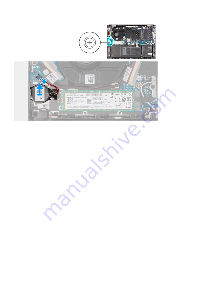
1. Disconnect the coin-cell battery from the I/O board.
2. Peel and lift the coin-cell battery from the palm-rest and keyboard assembly.

Installing the coin-cell battery

Prerequisites

If you are replacing a component, remove the existing component before performing the installation process.

About this task

The following image(s) indicate the location of the coin-cell battery and provides a visual representation of the installation
procedure.

22

Removing and installing components

Содержание P157G

Страница 1: ...Inspiron 14 5420 Service Manual Regulatory Model P157G Regulatory Type P157G001 P157G002 February 2022 Rev A00 ...

Страница 2: ...ential damage to hardware or loss of data and tells you how to avoid the problem WARNING A WARNING indicates a potential for property damage personal injury or death 2022 Dell Inc or its subsidiaries All rights reserved Dell EMC and other trademarks are trademarks of Dell Inc or its subsidiaries Other trademarks may be trademarks of their respective owners ...

Страница 3: ...able 18 Battery 19 Lithium ion battery precautions 19 Removing the battery 20 Installing the battery 20 Coin cell battery 21 Removing the coin cell battery 21 Installing the coin cell battery 22 Solid state drive 23 Removing the M 2 2230 solid state drive 23 Installing the M 2 2230 solid state drive 25 Removing the M 2 2280 solid state drive 26 Installing the M 2 2280 solid state drive 27 Memory m...

Страница 4: ...nd keyboard assembly 57 Removing the palm rest and keyboard assembly 57 Installing the palm rest and keyboard assembly 58 Chapter 3 Drivers and downloads 60 Chapter 4 System setup 61 Entering BIOS setup program 61 Navigation keys 61 Boot Sequence 62 System setup options 62 System and setup password 66 Assigning a system setup password 66 Deleting or changing an existing system setup password 67 Cl...

Страница 5: ...SupportAssist On board Diagnostics 72 Recovering the operating system 72 WiFi power cycle 72 Drain residual flea power perform hard reset 73 Chapter 6 Getting help and contacting Dell 74 Contents 5 ...

Страница 6: ...from the system board To enter Service Mode 1 Shut down your computer and disconnect the AC adapter 2 Hold B key on the keyboard and press the power button for 3 seconds or until the Dell logo appears on the screen 3 Press any key to continue NOTE If the power adapter has not been disconnected a message prompting you to remove the AC adapter appears on the screen Remove the AC adapter and then pre...

Страница 7: ...protection ESD is a major concern when you handle electronic components especially sensitive components such as expansion cards processors memory DIMMs and system boards Very slight charges can damage circuits in ways that may not be obvious such as intermittent problems or a shortened product life span As the industry pushes for lower power requirements and increased density ESD protection is an ...

Страница 8: ... plug the wrist strap s bonding wire into the tester while it is strapped to your wrist and push the button to test A green LED is lit if the test is successful a red LED is lit and an alarm sounds if the test fails Insulator Elements It is critical to keep ESD sensitive devices such as plastic heat sink casings away from internal parts that are insulators and often highly charged Working Environm...

Страница 9: ...he load Avoid twisting your body and back 6 Follow the same techniques in reverse to set the load down Exiting Service Mode Service Mode allows users to immediately cut off electricity from the computer and conduct repairs without disconnecting the battery cable from the system board To exit Service Mode 1 Connect the AC adapter to the power adapter port on your computer 2 Press the power button t...

Страница 10: ...netic surfaces Ensure that the screws are not left attached to such surfaces when replacing a component NOTE Screw color may vary with the configuration ordered Table 1 Screw list Component Secured to Screw type Quantity Screw image Base cover Palm rest and keyboard assembly M2x4 5 Base cover Palm rest and keyboard assembly M2x7 captive 2 Battery Palm rest and keyboard assembly M2x3 5 Solid state ...

Страница 11: ...ader Palm rest and keyboard assembly M2x3 1 USB C port bracket System board M2x4 2 Display hinges Palm rest and keyboard assembly M2 5x4 4 I O board Palm rest and keyboard assembly M2x3 1 System board Palm rest and keyboard assembly M2x1 8 2 Major components of Inspiron 14 5420 The following image shows the major components of Inspiron 14 5420 Removing and installing components 11 ...

Страница 12: ...C port bracket 3 System board 4 Coin cell battery 5 Left speaker 6 Heat sink 7 Memory 8 Palm rest and keyboard assembly 9 Display assembly 10 Touchpad 11 Touchpad bracket 12 I O board 12 Removing and installing components ...

Страница 13: ...e available according to warranty coverages purchased by the customer Contact your Dell sales representative for purchase options Base cover Removing the base cover Prerequisites 1 Follow the procedure in Before working inside your computer About this task NOTE Before removing the base cover ensure that there is no SD card installed in the SD card slot on your computer The following image s indica...

Страница 14: ...14 Removing and installing components ...

Страница 15: ... pry the base cover from the bottom left and continue to work on the sides to open the base cover 4 Lift and slide the base cover off the palm rest assembly 5 Disconnect the battery cable from the system board 6 Press and hold the power button for five seconds to ground the computer and drain the flea power Removing and installing components 15 ...

Страница 16: ...component remove the existing component before performing the installation process About this task The following image s indicate the location of the base cover and provides a visual representation of the installation procedure 16 Removing and installing components ...

Страница 17: ... cover to the palm rest assembly Next steps 1 Follow the procedure in After working inside your computer Battery cable Removing the battery cable Prerequisites 1 Follow the procedure in Before working inside your computer 2 Remove the base cover About this task The following image s indicate the location of the battery cable and provides a visual representation of the removal procedure Removing an...

Страница 18: ...battery cable from the battery 5 Lift the battery cable off the battery Installing the battery cable Prerequisites If you are replacing a component remove the existing component before performing the installation process About this task The following image s indicate the location of the battery cable and provides a visual representation of the installation procedure 18 Removing and installing comp...

Страница 19: ...t the AC power adapter from the system and operate the computer solely on battery power the battery is fully discharged when the computer no longer turns on when the power button is pressed Do not crush drop mutilate or penetrate the battery with foreign objects Do not expose the battery to high temperatures or disassemble battery packs and cells Do not apply pressure to the surface of the battery...

Страница 20: ...low the procedure in Before working inside your computer 2 Remove the base cover About this task NOTE Before removing the base cover ensure that there is no SD card installed in the SD card slot on your computer The following image s indicate the location of the battery and provides a visual representation of the removal procedure Steps 1 Peel the tape that secures the battery cable to the battery...

Страница 21: ...e the tape that secures the battery cable to the battery Next steps 1 Follow the procedure in After working inside your computer Coin cell battery Removing the coin cell battery Prerequisites 1 Follow the procedure in Before working inside your computer 2 Enter Service Mode 3 Remove the base cover About this task NOTE Before removing the base cover ensure that there is no SD card installed in the ...

Страница 22: ...nstalling the coin cell battery Prerequisites If you are replacing a component remove the existing component before performing the installation process About this task The following image s indicate the location of the coin cell battery and provides a visual representation of the installation procedure 22 Removing and installing components ...

Страница 23: ...ve Prerequisites 1 Follow the procedure in Before working inside your computer 2 Enter Service Mode 3 Remove the base cover About this task NOTE This procedure applies only to computers shipped with an M 2 2230 solid state drive installed NOTE The M 2 solid state drive installed on your computer depends on the configuration ordered The M 2 slot supports one of the following solid state drives M 2 ...

Страница 24: ...2230 solid state drive The following image s indicate the location of the M 2 2230 solid state drive and provides a visual representation of the removal procedure Steps 1 Remove the screw M2x3 that secures the M 2 2230 solid state drive bracket to the system board 2 Slide and lift the M 2 2230 solid state drive bracket off the system board 3 Turn over the M 2 2230 solid state drive bracket 4 Loose...

Страница 25: ...ounting bracket is provided if the M 2 2230 solid state is shipped with the computer If you are replacing the M 2 2230 solid state drive with a new M 2 2230 solid state drive use the existing mounting bracket to install the latter M 2 2280 solid state drive If you are replacing the M 2 2280 solid state drive shipped with the computer with an M 2 2230 solid state drive a mounting bracket for the M ...

Страница 26: ...de the M 2 2230 solid state drive bracket into the M 2 card slot on the system board 5 Replace the screw M2x3 that secures the M 2 2230 solid state drive bracket to the system board Next steps 1 Install the base cover 2 Exit Service Mode 3 Follow the procedure in After working inside your computer Removing the M 2 2280 solid state drive Prerequisites 1 Follow the procedure in Before working inside...

Страница 27: ...he M 2 2280 solid state drive shipped with the computer with an M 2 2230 solid state drive a mounting bracket for the M 2 2230 solid state drive is required Please contact Dell support to purchase the mounting bracket for the M 2 2230 solid state drive The following image s indicate the location of the M 2 2280 solid state drive and provides a visual representation of the removal procedure Steps 1...

Страница 28: ...mputer with an M 2 2230 solid state drive a mounting bracket for the M 2 2230 solid state drive is required Please contact Dell support to purchase the mounting bracket for the M 2 2230 solid state drive The following image s indicate the location of the M 2 2280 solid state drive and provides a visual representation of the installation procedure Steps 1 Align the notch on the M 2 2280 solid state...

Страница 29: ...ndicate the location of the memory module and provides a visual representation of the removal procedure Steps 1 Lift the Mylar to access the memory module 2 Using your fingertips carefully spread apart the securing clips on each end of the memory module slot until the memory module pops up 3 Remove the memory module from the memory module slot on the system board Removing and installing components...

Страница 30: ...entation of the installation procedure Steps 1 Lift the Mylar to access the memory module slot 2 Align the notch on the memory module with the tab on the memory module slot on the system board 3 Slide the memory module into the memory module slot on the system board 4 Press down on the memory module till the securing clips click locking the memory module in place Next steps 1 Install the base cove...

Страница 31: ...ing image s indicate the location of the wireless card and provides a visual representation of the removal procedure Steps 1 Remove the screw M2x3 that secures the wireless card bracket to the wireless card and system board 2 Lift the wireless card bracket off the wireless card 3 Disconnect the antenna cables from the wireless card 4 Slide and remove the wireless card from the M 2 card slot on the...

Страница 32: ...ireless card Table 2 Antenna cable color scheme Connectors on the wireless card Antenna cable color Silkscreen marking Main White MAIN white triangle Auxiliary Black AUX black triangle 2 Place the wireless card bracket on the wireless card 3 Align the notch on the wireless card with the tab on the M 2 card slot on the system board 4 Slide the wireless card into the M 2 card slot on the system boar...

Страница 33: ...r adapter port and provides a visual representation of the removal procedure Steps 1 Remove the two screws M2 5x4 that secure the right display hinge to the system board 2 Open the display hinge at an angle of 90 degrees 3 Disconnect the power adapter port cable from the system board 4 Peel the tape that secures the power adapter port cable to the system board 5 Remove the power adapter port cable...

Страница 34: ...outing guide on the palm rest and keyboard assembly 3 Adhere the tape that secures the power adapter port cable to the system board 4 Connect the power adapter port cable to the system board 5 Close the right display hinge and align the screw holes on the right display hinge with the screw holes on the system board and the palm rest and keyboard assembly 6 Replace the two M2 5x4 screws that secure...

Страница 35: ...rocedure in Before working inside your computer 2 Enter Service Mode 3 Remove the base cover About this task The following image s indicate the location of the display assembly and provides a visual representation of the removal procedure Removing and installing components 35 ...

Страница 36: ...m board 2 Lift the latch and disconnect the display cable from the connector on the system board 3 Remove the two screws M2 5x4 that secure the right display hinge to the system board 4 Pry open the right display hinge at an angle of 90 degrees 36 Removing and installing components ...

Страница 37: ...damaging the display do not slide the palm rest and keyboard assembly over the display assembly Installing the display assembly Prerequisites If you are replacing a component remove the existing component before performing the installation process About this task The following image s indicate the location of the display assembly and provides a visual representation of the installation procedure R...

Страница 38: ...5x4 that secure the left display hinge to the palm rest and keyboard assembly 5 Close the right display hinge and align the screw holes on the right display hinge with the screw holes on the system board 6 Replace the two screws M2 5x4 that secure the right display hinge to the palm rest and keyboard assembly 7 Connect the display cable to the connector on the system board and close the latch 8 Ad...

Страница 39: ...t display hinge at an angle of 90 degrees 3 Lift the I O board cable connector latch and disconnect the I O board cable from the I O board 4 Lift the power button with fingerprint reader cable connector latch and disconnect the power button with fingerprint reader cable from the I O board NOTE This step is only applicable for computers shipped with the optional fingerprint reader 5 Remove the scre...

Страница 40: ... I O board to the palm rest and keyboard assembly 5 Close the left display hinge and align the screw holes on the left display hinge with the screw holes on the I O board 6 Replace the two screws M2 5x4 that secure the left display hinge to the I O board 7 Connect the I O board cable to the connector on the I O board and close the latch 8 Connect the power button with fingerprint reader cable to t...

Страница 41: ... and cannot be separated for individual replacement Services will replace the speakers and the wireless antennas as an assembly part The following image s indicate the location of the speakers and provides a visual representation of the removal procedure Steps 1 Peel off the tapes that secure the antenna cables to the palm rest and keyboard assembly 2 Lift the antenna cables and move them out of t...

Страница 42: ...aker cables from the routing guides on the palm rest and keyboard assembly 9 Lift the speakers along with their cables off the palm rest and keyboard assembly Installing the speakers Prerequisites If you are replacing a component remove the existing component before performing the installation process About this task The following image s indicate the location of the speakers and provides a visual...

Страница 43: ... them to the palm rest and keyboard assembly Next steps 1 Install the battery 2 Install the base cover 3 Follow the procedure in After working inside your computer Touchpad Removing the touchpad Prerequisites 1 Follow the procedure in Before working inside your computer 2 Remove the base cover 3 Remove the battery About this task The following image s indicate the location of the touchpad and prov...

Страница 44: ...following image s indicate the location of the touchpad and provides a visual representation of the installation procedure Steps 1 Place the touchpad on the palm rest and keyboard assembly 2 Turn the computer over and open the display to ensure that the touchpad is equally aligned on all sides NOTE The image below shows the proper touchpad alignment for your computer 3 Close the display and turn t...

Страница 45: ...2 Install the base cover 3 Follow the procedure in After working inside your computer Fan Removing the fan Prerequisites 1 Follow the procedure in Before working inside your computer 2 Enter Service Mode 3 Remove the base cover About this task The following image s indicate the location of the fan and provides a visual representation of the removal procedure Steps 1 Disconnect the fan cable from t...

Страница 46: ...2 Align the screw holes on the fan with the screw holes on the palm rest and keyboard assembly 3 Replace the two screws M2x3 that secure the fan to the palm rest and keyboard assembly 4 Connect the fan cable to the system board Next steps 1 Install the base cover 2 Exit Service Mode 3 Follow the procedure in After working inside your computer Heat sink Removing the heat sink UMA Prerequisites 1 Fo...

Страница 47: ...r 4 3 2 1 loosen the four captive screws that secure the heat sink to the system board NOTE The number of screws varies depending on the configuration ordered 2 Lift the heat sink from the system board Installing the heat sink UMA Prerequisites If you are replacing a component remove the existing component before performing the installation process About this task NOTE If either the system board o...

Страница 48: ...he heat sink discrete Prerequisites 1 Follow the procedure in Before working inside your computer 2 Enter Service Mode 3 Remove the base cover About this task CAUTION The heat sink may become hot during normal operation Allow sufficient time for the heat sink to cool before you touch it NOTE For maximum cooling of the processor do not touch the heat transfer areas on the heat sink The oils in your...

Страница 49: ...iscrete Prerequisites If you are replacing a component remove the existing component before performing the installation process About this task NOTE If either the system board or the heat sink is replaced use the thermal grease provided in the kit to ensure that thermal conductivity is achieved The following image s indicate the location of the heat sink discrete and provides a visual representati...

Страница 50: ...over 2 Exit Service Mode 3 Follow the procedure in After working inside your computer Power button with optional fingerprint reader Removing the power button with optional fingerprint reader Prerequisites 1 Follow the procedure in Before working inside your computer 2 Enter Service Mode 3 Remove the base cover 4 Remove the I O board About this task The following image s indicate the location of th...

Страница 51: ...yboard assembly Installing the power button with optional fingerprint reader Prerequisites If you are replacing a component remove the existing component before performing the installation process About this task The following image s indicate the location of the power button with optional fingerprint reader and provides a visual representation of the installation procedure Removing and installing...

Страница 52: ...xit Service Mode 4 Follow the procedure in After working inside your computer System board Removing the system board Prerequisites 1 Follow the procedure in Before working inside your computer 2 Remove the base cover 3 Remove the memory module 4 Remove the M 2 2230 solid state drive or M 2 2280 solid state drive 5 Remove the wireless card 6 Remove the speakers 7 Remove the touchpad About this task...

Страница 53: ...hpad cable 6 battery cable 7 wireless card cable 8 speaker cable 9 M 2 2230 2280 solid state drive 10 I O board cable 11 fan cable The following image s indicate the location of the system board and provides a visual representation of the removal procedure Removing and installing components 53 ...

Страница 54: ...m the system board 3 Peel off the tapes that secure the I O board cable and antenna cables to the palm rest and keyboard assembly 4 Lift the I O board cable and antenna cables and move them out of the way 5 Peel off the tape that secures the speaker cable to the palm rest and keyboard assembly 54 Removing and installing components ...

Страница 55: ...the system board at angle off the palm rest and keyboard assembly to clear the ports from the port openings Installing the system board Prerequisites If you are replacing a component remove the existing component before performing the installation process About this task The following image indicates the connectors on your system board 1 display cable 2 power adapter port cable 3 keyboard backligh...

Страница 56: ...rd with the screw holes on the palm rest and keyboard assembly 3 Replace the two screws M2x1 8 that secure the system board to the palm rest and keyboard assembly 4 Connect the display cable to the system board and close the latch to secure the cable 5 Adhere the tape that secures the display cable to the system board 56 Removing and installing components ...

Страница 57: ... the wireless card 4 Install the M 2 2230 solid state drive or M 2 2280 solid state drive 5 Install the memory module 6 Install the base cover 7 Follow the procedure in After working inside your computer Palm rest and keyboard assembly Removing the palm rest and keyboard assembly Prerequisites 1 Follow the procedure in Before working inside your computer 2 Remove the base cover 3 Remove the batter...

Страница 58: ...eyboard assembly Prerequisites If you are replacing a component remove the existing component before performing the installation process About this task The following image s indicate the location of the palm rest and keyboard assembly and provides a visual representation of the installation procedure 58 Removing and installing components ...

Страница 59: ...power adapter port 5 Install the power button with optional fingerprint reader 6 Install the system board 7 Install the I O board 8 Install the fan 9 Install the coin cell battery 10 Install the wireless card 11 Install the M 2 2230 solid state drive or M 2 2280 solid state drive 12 Install the memory module 13 Install the battery 14 Install the base cover 15 Follow the procedure in After working ...

Страница 60: ...rivers and downloads When troubleshooting downloading or installing drivers it is recommended that you read the Dell Knowledge Based article Drivers and Downloads FAQ 000123347 3 60 Drivers and downloads ...

Страница 61: ...ling base devices Entering BIOS setup program Steps 1 Turn on your computer 2 Press F2 immediately to enter the BIOS setup program NOTE If you wait too long and the operating system logo appears continue to wait until you see the desktop Then turn off your computer and try again Navigation keys NOTE For most of the System Setup options changes that you make are recorded but do not take effect unti...

Страница 62: ... Overview BIOS Version Displays the BIOS version number Service Tag Displays the Service Tag of the computer Asset Tag Displays the Asset Tag of the computer Manufacture Date Displays the manufacture date of the computer Ownership Date Displays the ownership date of the computer Express Service Code Displays the express service code of the computer Ownership Tag Displays the ownership tag of the c...

Страница 63: ...mory Displays the video memory information of the computer Wi Fi Device Displays the Wi Fi device installed in the computer Native Resolution Displays the native resolution of the computer Video BIOS Version Displays the video BIOS version of the computer Audio Controller Displays the audio controller information of the computer Bluetooth Device Displays whether a Bluetooth device is installed in ...

Страница 64: ...puter date in MM DD YYYY format Changes to the date take effect immediately Time Sets the computer time in HH MM SS 24 hour format You can switch between 12 hour and 24 hour clock Changes to the time take effect immediately Camera Enable Camera Enables or disables the camera By default Enable Camera is selected Audio Enables or disables all integrated audio controller Default ON Enable Microphone ...

Страница 65: ...ange or delete the system password Internal HDD 1 Password Enables the user to set change or delete the Internal HDD 1 password Table 10 System setup options Update Recovery menu Update Recovery SupportAssist OS Recovery Enables or disables the boot flow for SupportAssist OS Recovery tool in the event of certain system error Default ON BIOSConnect Enables or disables cloud Service OS recovery if t...

Страница 66: ...ent Log Clear Thermal Event Log Select keep or clear Thermal events Default Keep Power Event Log Clear POWER Event Log Select keep or clear Power events Default Keep System and setup password Table 14 System and setup password Password type Description System password Password that you must enter to log on to your system Setup password Password that you must enter to access and make changes to the...

Страница 67: ... password You cannot delete or change an existing System or Setup password if the Password Status is Locked About this task To enter the System Setup press F12 immediately after a power on or reboot Steps 1 In the System BIOS or System Setup screen select System Security and press Enter The System Security screen is displayed 2 In the System Security screen verify that Password Status is Unlocked ...

Страница 68: ...load to download the BIOS file for your computer 7 After the download is complete browse the folder where you saved the BIOS update file 8 Double click the BIOS update file icon and follow the on screen instructions For more information see knowledge base article 000124211 at www dell com support Updating the BIOS using the USB drive in Windows Steps 1 Follow the procedure from step 1 to step 6 in...

Страница 69: ... following USB drive formatted to the FAT32 file system key does not have to be bootable BIOS executable file that you downloaded from the Dell Support website and copied to the root of the USB drive AC power adapter that is connected to the computer Functional computer battery to flash the BIOS Perform the following steps to perform the BIOS update flash process from the F12 menu CAUTION Do not t...

Страница 70: ...cks and cells Do not apply pressure to the surface of the battery Do not bend the battery Do not use tools of any type to pry on or against the battery If a battery gets stuck in a device as a result of swelling do not try to free it as puncturing bending or crushing a battery can be dangerous Do not attempt to reassemble a damaged or swollen battery into a laptop Swollen batteries that are covere...

Страница 71: ...following diagnostic light codes and recommended solutions are intended for Dell service technicians to troubleshoot problems You should only perform troubleshooting and repairs as authorized or directed by the Dell technical support team Damage due to servicing that is not authorized by Dell is not covered by your warranty Table 15 Diagnostic light codes Diagnostic light codes Amber white Problem...

Страница 72: ...View error messages that indicate if problems were encountered during the test NOTE Some tests for specific devices require user interaction Ensure that you are present at the computer terminal when the diagnostic tests are performed For more information see SupportAssist Pre Boot System Performance Check Recovering the operating system When your computer is unable to boot to the operating system ...

Страница 73: ...or replacing any components in your computer Draining residual flea power also known as a performing a hard reset is also a common troubleshooting step if your computer does not power on or boot into the operating system To drain residual flea power perform a hard reset Steps 1 Turn off your computer 2 Disconnect the power adapter from your computer 3 Remove the base cover 4 Remove the battery 5 P...

Страница 74: ... Service Tag or Express Service Code at www dell com support For more information on how to find the Service Tag for your computer see Locate the Service Tag on your computer Dell knowledge base articles for a variety of computer concerns 1 Go to www dell com support 2 On the menu bar at the top of the Support page select Support Knowledge Base 3 In the Search field on the Knowledge Base page type...

Отзывы: