background image

Back to Contents Page


 Card Cage  

Dell™ Latitude™ E6400 and E6400 ATG and 


Mobile Workstation Precision™ M2400 Service Manual


Removing the Card Cage 


Replacing the Card Cage 


Removing the Card Cage  


1.

Follow the procedures in 

Before Working on Your Computer

.  


2.

Remove the bottom of the base assembly (see 

Removing the Bottom of the Base Assembly

).  


3.

Remove the modular drive (see 

Removing the Modular Drive

).  


4.

Remove the hinge covers (see 

Removing the Hinge Covers

).  


5.

Remove the heatsink assembly (see 

Removing the Processor Heatsink Assembly

).  


6.

Remove the display assembly (see 

Removing the Display Assembly (E6400 and M2400)

 or 

Removing the Display Assembly (E6400 ATG)

).  


7.

Remove the LED cover (see 

Removing the LED Cover

).  


8.

Remove the keyboard (see 

Removing the Keyboard

).  


9.

Remove the right speaker grill (see 

Removing the Right Speaker Grill/Fingerprint Reader Assembly

).  


10.

Remove the palm rest assembly (

Removing the Palm Rest Assembly

).  


11.

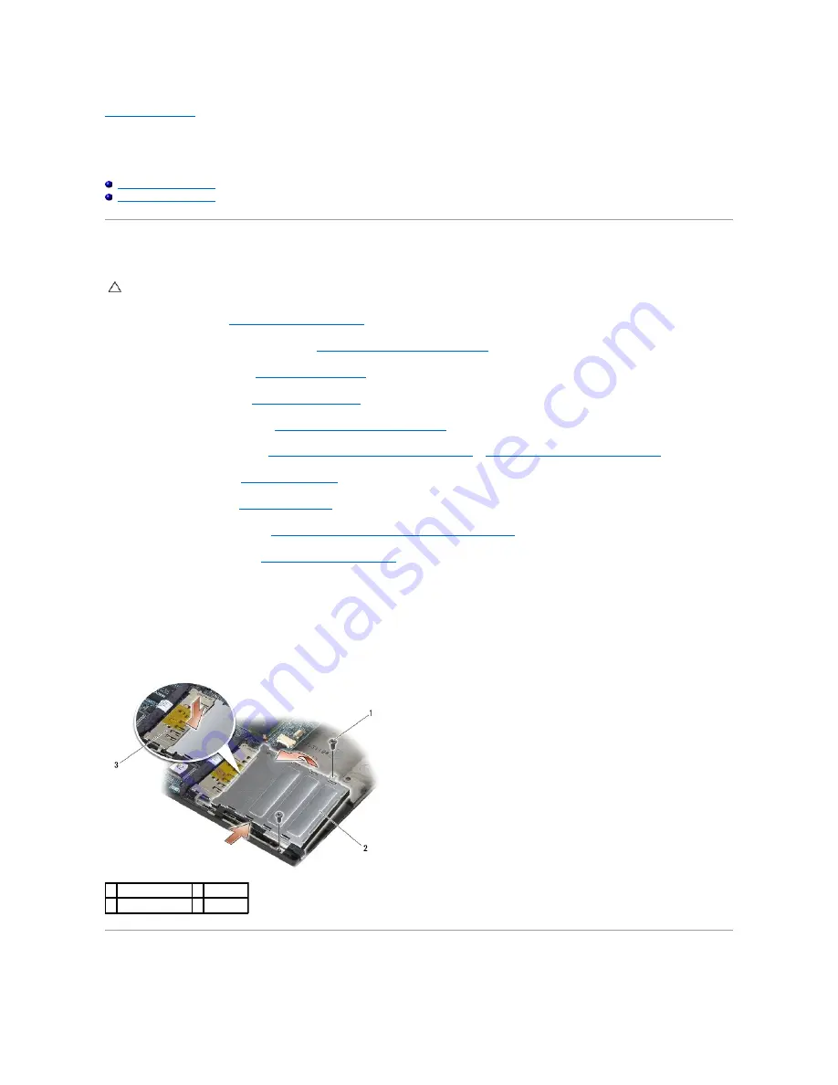
If a card is in the card cage, remove the card.  


12.

Remove the two M2 x 3 screws.  


13.

Press down on the connector-end of the card cage, then grasp each side of the card cage and push it towards the back of the laptop.  


14.

Pivot the card cage up to a 45-degree angle, then lift it up from the connector and laptop.  


Replacing the Card Cage  


CAUTION: 

Before you begin any of the procedures in this section, follow the safety instructions that shipped with your computer.

1  M2 x 3 screws (2)  2  card cage 

3  connector 


Содержание Latitude E6400 ATG

Страница 1: ...rosoft Corporation in the United States and or other countries Other trademarks and trade names may be used in this document to refer to either the entities claiming the marks and names or their products Dell Inc disclaims any proprietary interest in trademarks and trade names other than its own September 2009 Rev A02 Troubleshooting Working on Your Computer Base Assembly Hinge Covers Hard Drive W...

Страница 2: ...assembly see Removing the Display Assembly E6400 and M2400 or Removing the Display Assembly E6400 ATG 7 Remove the LED cover see Removing the LED Cover 8 Remove the keyboard see Removing the Keyboard 9 Remove the right speaker grill see Removing the Right Speaker Grill Fingerprint Reader Assembly 10 Remove the palm rest assembly Removing the Palm Rest Assembly 11 Remove the card cage see Removing ...

Страница 3: ... see Replacing the Keyboard 8 Replace the LED cover see Replacing the LED Cover 9 Replace the display assembly see Replacing the Display Assembly E6400 and M2400 or Replacing the Display Assembly E6400 ATG 10 Replace the heatsink assembly see Replacing the Processor Heatsink Assembly 11 Replace the hinge covers see Replacing the Hinge Covers 12 Replace the modular drive see Replacing the Modular D...

Страница 4: ...bly Replacing the Bottom of the Base Assembly 1 Slide the bottom of the base assembly into place 2 Tighten the captive screw 3 Follow the procedures in After Working on Your Computer Removing the Base Assembly 1 Follow the procedures in Before Working on Your Computer 2 Remove the bottom of the base assembly see Removing the Bottom of the Base Assembly 3 Remove the card in the WWAN FCM card slot i...

Страница 5: ... the RJ 11 modem connector see Removing the RJ 11 Modem Connector 20 Remove the I O card see Removing the I O Card Replacing the Base Assembly 1 Replace the I O card see Replacing the I O Card 2 Replace the RJ 11 modem connector see Replacing the RJ 11 Modem Connector 3 Replace the modem see Replacing the Modem 4 Replace the system board see Replacing the System Board Assembly 5 Replace the coin c...

Страница 6: ...er Working on Your Computer 21 Flash update the BIOS see Flashing the BIOS for more information 22 Enter the system setup program to update the BIOS on the new system board with the computer Service Tag For information on the system setup program see the Dell Technology Guide on your computer or at support dell com Back to Contents Page NOTE If you use a BIOS update program disc to flash the BIOS ...

Страница 7: ...moving the Display Assembly E6400 and M2400 or Removing the Display Assembly E6400 ATG 8 Remove the LED cover see Removing the LED Cover 9 Remove the keyboard see Removing the Keyboard 10 Remove the right speaker grill see Removing the Right Speaker Grill Fingerprint Reader Assembly 11 Remove the palm rest assembly see Removing the Palm Rest Assembly 12 Remove the card cage see Removing the Card C...

Страница 8: ...d Cage 9 Replace the palm rest assembly see Replacing the Palm Rest Assembly 10 Replace the right speaker grill see Replacing the Right Speaker Grill Fingerprint Reader Assembly 11 Replace the keyboard see Replacing the Keyboard 12 Replace the LED cover see Replacing the LED Cover 13 Replace the display assembly see Replacing the Display Assembly E6400 and M2400 or Replacing the Display Assembly E...

Страница 9: ...the hard drive see Replacing the Hard Drive 18 Replace the bottom of the base assembly see Replacing the Bottom of the Base Assembly 19 Follow the procedures in After Working on Your Computer Back to Contents Page ...

Страница 10: ... section follow the safety instructions that shipped with your computer CAUTION Many repairs may only be done by a certified service technician You should only perform troubleshooting and simple repairs as authorized in your product documentation or as directed by the online or telephone service and support team Damage due to servicing that is not authorized by Dell is not covered by your warranty...

Страница 11: ...battery slice or on support dell com l To remove a cool slice see the documentation that shipped with your cool slice or on support dell com l To remove a port cover from the E6400 ATG lift up and ease the port cover away from the connectors along the back of the computer 9 Turn the computer topside up open the display and press the power button to ground the system board After Working on Your Com...

Страница 12: ... from the E6400 ATG fit the port cover into the connectors on the back of the computer 3 Connect any telephone or network cables to your computer 4 Replace the battery Slide the battery into the battery bay until it clicks into place 5 Connect your computer and all attached devices to their electrical outlets 6 Turn on your computer Back to Contents Page ...

Страница 13: ...drive Flashing the BIOS From the Hard Drive 1 Ensure that the AC adapter is plugged in the main battery is properly installed and a network cable is attached 2 Turn on the computer 3 Locate the latest BIOS update file for your computer at support dell com 4 Click Download Now to download the file 5 If the Export Compliance Disclaimer window appears click Yes I Accept this Agreement The File Downlo...

Страница 14: ...Back to Contents Page ...

Страница 15: ...0 or Removing the Display Assembly E6400 ATG 7 Remove the LED cover see Removing the LED Cover 8 Remove the keyboard see Removing the Keyboard 9 Remove the right speaker grill see Removing the Right Speaker Grill Fingerprint Reader Assembly 10 Remove the palm rest assembly Removing the Palm Rest Assembly 11 If a card is in the card cage remove the card 12 Remove the two M2 x 3 screws 13 Press down...

Страница 16: ...lay assembly see Replacing the Display Assembly E6400 and M2400 or Replacing the Display Assembly E6400 ATG 8 Replace the heatsink assembly see Replacing the Processor Heatsink Assembly 9 Replace the hinge covers see Replacing the Hinge Covers 10 Replace the modular drive see Replacing the Modular Drive 11 Replace the bottom of the base assembly see Replacing the Bottom of the Base Assembly 12 Fol...

Страница 17: ...m board Replacing the Coin Cell Battery 1 Connect the coin cell battery cable to the system board 2 Insert the coin cell battery into the computer If you are installing the same coin cell battery you removed slide the battery under the tab then press down to seal the tape on bottom If you are installing a new coin cell battery first remove the adhesive backing paper from the coin cell battery Slid...

Страница 18: ...ace the bottom of the base assembly see Replacing the Bottom of the Base Assembly 4 Follow the procedures in After Working on Your Computer Back to Contents Page 1 coin cell battery 2 coin cell battery cable ...

Страница 19: ... To loosen the ZIF socket use a small flat blade screwdriver and rotate the ZIF socket cam screw counterclockwise until it comes to the cam stop CAUTION Before you begin the following procedure follow the safety instructions that shipped with your computer 1 processor module NOTICE To avoid damage to the processor hold the screwdriver so that it is perpendicular to the processor when turning the c...

Страница 20: ...dure follow the safety instructions that shipped with your computer NOTICE Do not touch the processor die Press and hold the processor down on the substrate on which the die is mounted while turning the cam screw to prevent intermittent contact between the cam screw and processor NOTICE Ensure that the cam lock is in the fully open position before seating the processor module Seating the processor...

Страница 21: ...Replacing the Processor Heatsink Assembly 1 Place the vent end of the assembly into the computer at an angle then connect the fan cable to the system board and set the screw end of the assembly in place 2 Align the four captive screws on the processor heatsink assembly with the screw holes on the system board 3 In sequential order tighten the four captive screws to secure the processor heatsink as...

Страница 22: ...6 Follow the procedures in After Working on Your Computer Back to Contents Page ...

Страница 23: ...oving the Display Assembly E6400 ATG 8 Remove the LED cover see Removing the LED Cover 9 Remove the keyboard see Removing the Keyboard 10 Remove the right speaker grill see Removing the Right Speaker Grill Fingerprint Reader Assembly 11 Remove the palm rest assembly see Removing the Palm Rest Assembly 12 Remove the card cage see Removing the Card Cage 13 Remove the system board see Removing the Sy...

Страница 24: ...lace the keyboard see Replacing the Keyboard 11 Replace the LED cover see Replacing the LED Cover 12 Replace the display assembly see Replacing the Display Assembly E6400 and M2400 or Replacing the Display Assembly E6400 ATG 13 Replace the heatsink assembly see Replacing the Processor Heatsink Assembly 14 Replace the hinge covers see Replacing the Hinge Covers 15 Replace the modular drive see Repl...

Страница 25: ...Back to Contents Page ...

Страница 26: ...2400 Removing the Display Bezel E6400 ATG Replacing the Display Bezel E6400 ATG Removing the CCFL Display Panel and Brackets E6400 and M2400 Replacing the CCFL Display Panel and Brackets E6400 and M2400 Removing the LED Display Panel and Brackets E6400 and M2400 Replacing the LED Display Panel and Brackets E6400 and M2400 Removing the Display Panel and Brackets E6400 ATG Replacing the Display Pane...

Страница 27: ...antenna cables in the base assembly cable holders next to the card slot 6 Connect the display cable to the display cable connector on the system board 7 Replace the two M2 5 x 5 mm screws on the hinges 8 Replace the hinge covers see Replacing the Hinge Covers 9 Replace the bottom of the base assembly see Replacing the Bottom of the Base Assembly 10 Follow the procedures in After Working on Your Co...

Страница 28: ...s on the display assembly away from the base assembly 2 Align the display hinges with the holes in the base of the computer and lower the display into place 3 Close the display and turn the computer upside down 4 Route the display cable touch screen cable and wireless WLAN WWAN and WPAN cables Fit the cables under each tab in their respective routing 1 M2 5 x 5 mm screws 2 2 touch screen cable 3 d...

Страница 29: ...ll up on the bezel to release the side bezel snaps See the arrows labeled 1 in the following illustration 6 For the top right corner of the bezel push out to release the corner bezel snap See the arrow labeled 2 in the following illustration 7 For the lower right corner push out with force then gently pull up to release the corner bezel snap See the arrows labeled 3 in the following illustration 8...

Страница 30: ...display bezel 2 Simultaneously push in on the right and left sides of the bezel to engage the side bezel snaps 1 right side of display bezel 2 top of display bezel 3 left side of display bezel 4 bottom of display bezel 5 display panel CAUTION Before you begin the following procedure follow the safety instructions that shipped with your computer 1 opening on display bezel 2 latch hook on display pa...

Страница 31: ...2 in the following illustration 7 For the lower right corner push out with force then gently pull up to release the corner bezel snap See the arrows labeled 3 in the following illustration 8 For the bottom of the bezel push in toward the display panel starting with the lower right corner snap then the middle bottom snaps and then the lower left corner snap See the arrows labeled 4 through 6 in the...

Страница 32: ...vers see Replacing the Hinge Covers 7 Replace the bottom of the base assembly see Replacing the Bottom of the Base Assembly 8 Follow the procedures in After Working on Your Computer Removing the CCFL Display Panel and Brackets E6400 and M2400 1 Follow the instructions in Before Working on Your Computer 1 right side of display bezel 2 top of display bezel 3 left side of display bezel 4 display pane...

Страница 33: ...ver and carefully lay the display panel flat on your workspace Be careful to avoid damaging the display panel with the hinges and cables on the display cover 8 Disconnect the inverter backlight cable from the inverter 9 Disconnect the display cable Squeeze the release tabs together then pull the cable out of the connector 10 Remove four M2 x 3 mm screws from the right bracket and four M2 x 3 mm sc...

Страница 34: ...place the hinge covers see Replacing the Hinge Covers 10 Replace the bottom of the base assembly see Replacing the Bottom of the Base Assembly 11 Follow the procedures in After Working on Your Computer Removing the LED Display Panel and Brackets E6400 and M2400 1 Follow the instructions in Before Working on Your Computer 2 Remove the bottom of the base assembly see Removing the Bottom of the Base ...

Страница 35: ...hinges and cables on the display cover 8 Use the pull tab to disconnect the display cable 9 Remove two M2 x 3 mm screws from the right bracket and two M2 x 3 mm screws from the left bracket Replacing the LED Display Panel and Brackets E6400 and M2400 1 M2 5 x 5 mm screws 4 2 display panel 3 display cover 1 display cable connector 2 display cable 3 underside of display panel 1 display panel 2 brack...

Страница 36: ...f the base assembly see Removing the Bottom of the Base Assembly 3 Remove the hinge covers see Removing the Hinge Covers 4 Remove the display assembly see Removing the Display Assembly E6400 ATG 5 Remove the display bezel see Removing the Display Bezel E6400 ATG 6 Remove the four M2 5 x 5 mm screws from the display panel 7 Lift the display panel out of the display cover and lay the display panel f...

Страница 37: ...splay panel 5 Place the display panel in display cover Use the alignment posts in the display cover to align each bracket 6 Replace the four M2 5 x 5 mm screws that secure the display panel to the display cover 1 display cable 2 display connector release tabs 3 underside of display panel 4 touch screen cable touch screen display panels only 5 touch screen cable connector touch screen display panel...

Страница 38: ...play Assembly E6400 and M2400 5 Remove the display bezel see Removing the Display Bezel E6400 and M2400 6 Remove the two M2 x 3 mm screws from the display inverter 7 Disconnect the two display inverter connectors 8 Lift the display inverter out of the display cover Replacing the Display Inverter E6400 and M2400 1 Connect the two display inverter connectors to the display inverter 2 Replace the two...

Страница 39: ...400 or Removing the LED Display Panel and Brackets E6400 and M2400 7 Remove the two M2 5 x 5 mm screws from the right hinge and the two M2 5 x 5 mm screws from the left hinge 8 Unthread the cables from each hinge and remove the hinge Replacing the Display Hinges E6400 and M2400 1 Thread the cables into each hinge then slide the hinge onto the display cover Use the alignment pins on the display cov...

Страница 40: ...he Base Assembly 3 Remove the hinge covers see Removing the Hinge Covers 4 Remove the display assembly see Removing the Display Assembly E6400 ATG 5 Remove the display bezel see Removing the Display Bezel E6400 ATG 6 Remove the display panel see Removing the Display Panel and Brackets E6400 ATG 7 Remove the two M2 5 x 5 mm screws from the right hinge and the two M2 5 x 5 mm screws from the left hi...

Страница 41: ...Assembly 3 Remove the hinge covers see Removing the Hinge Covers 4 Remove the display assembly see Removing the Display Assembly E6400 and M2400 or Removing the Display Assembly E6400 ATG 5 Remove the display bezel see Removing the Display Bezel E6400 and M2400 or Removing the Display Bezel E6400 ATG 6 Lift the small connector lever on the microphone cable 7 Loosen the captive screw and carefully ...

Страница 42: ...ur Computer 2 Remove the bottom of the base assembly see Removing the Bottom of the Base Assembly 3 Remove the hinge covers see Removing the Hinge Covers 4 Remove the display assembly see Removing the Display Assembly E6400 and M2400 or Removing the Display Assembly E6400 ATG 5 Remove the display bezel see Removing the Display Bezel E6400 and M2400 or Removing the Display Bezel E6400 ATG 6 Lift th...

Страница 43: ...ing the Bottom of the Base Assembly 9 Follow the procedures in After Working on Your Computer Removing the Latch Hook Assembly 1 Follow the instructions in Before Working on Your Computer 2 Remove the bottom of the base assembly see Removing the Bottom of the Base Assembly 3 Remove the hinge covers see Removing the Hinge Covers 4 Remove the display assembly see Removing the Display Assembly E6400 ...

Страница 44: ...ving the Bottom of the Base Assembly 3 Remove the hinge covers see Removing the Hinge Covers 4 Remove the display assembly see Removing the Display Assembly E6400 and M2400 or Removing the Display Assembly E6400 ATG 5 Remove the display bezel see Removing the Display Bezel E6400 and M2400 or Removing the Display Bezel E6400 ATG 6 Remove the display panel from the display cover see Removing the CCF...

Страница 45: ...lay Bezel E6400 and M2400 or Replacing the Display Bezel E6400 ATG 4 Replace the display assembly see Replacing the Display Assembly E6400 and M2400 or Replacing the Display Assembly E6400 ATG 5 Replace the hinge covers see Replacing the Hinge Covers 6 Replace the bottom of the base assembly see Replacing the Bottom of the Base Assembly 7 Follow the procedures in After Working on Your Computer Bac...

Страница 46: ...k assembly to remove it Replacing the Fan 1 Lift the flap on the heatsink assembly and insert the fan at an angle 2 Align the screws holes in the fan with the screw holes in the processor heatsink assembly 3 Replace the two M2 5 x 5 mm screws to secure the fan to the processor heatsink assembly 4 Connect the fan cable to the system board 5 Replace the bottom of the base assembly see Removing the B...

Страница 47: ...Back to Contents Page ...

Страница 48: ... 3 Remove the M2 x 3 mm screw The FCM pops up at a 45 degree angle 4 Slide the FCM out of the card connector on the system board Removing an FCM from the WPAN UWB FCM Slot 1 Follow the procedures in Working on Your Computer 2 Remove the bottom of the base assembly see Removing the Bottom of the Base Assembly 3 Remove the M2 5 x 5 mm screw from the left hinge cover and slide it forward then lift to...

Страница 49: ...installing this module ensure that the antenna cables are not under the card Place the antenna cables in the holder next to the module Installing the module on top of these antenna cables may cause damage to your computer NOTICE The connectors are keyed to ensure correct insertion If you feel resistance check the connectors on the module and on the system board and realign the module NOTICE An FCM...

Страница 50: ...ace the bottom of the base assembly see Replacing the Bottom of the Base Assembly 6 Follow the procedures in After Working on Your Computer Back to Contents Page 1 holder by module 2 blue antenna cable 3 FCM ...

Страница 51: ... the M3 x 3 mm screw on the hard drive bezel 6 Remove the hard drive bezel NOTE Dell does not guarantee compatibility or provide support for hard drives obtained from sources other than Dell CAUTION Before you begin any of the procedures in this section follow the safety instructions that shipped with your computer CAUTION Do not touch the metal housing of the hard drive if you remove the hard dri...

Страница 52: ...down 3 Remove the two M3 x 3 mm screws 4 Slide the hard drive out of the base assembly 1 hard drive bezel 2 pin on bezel bracket 3 hard drive 4 M3 x 3 mm screw CAUTION Before you begin any of the procedures in this section follow the safety instructions that shipped with your computer NOTICE Hard drives are extremely fragile Exercise care when handling the hard drive NOTICE Use firm and even press...

Страница 53: ...up at an angle and slide the tabs on the cover out from the carrier 9 Slide the hard drive away from the connector lift it up at an angle and then slide it out of the hard drive carrier 1 hard drive 2 bottom of base assembly 3 M3 x 3 mm screws 2 1 hard drive bezel 2 pin on bezel bracket 3 hard drive 4 M3 x 3 mm screw 1 M2 5 x 5 mm screws 2 2 cover 3 tabs 2 4 hard drive carrier ...

Страница 54: ...s section follow the safety instructions that shipped with your computer NOTICE Hard drives are extremely fragile Exercise care when handling the hard drive NOTICE Use firm and even pressure to slide the hard drive into place Excessive force may result in damage to the connector NOTICE The top and bottom of the blue bumper are different The top is flat with slight ridges and the bottom has protrud...

Страница 55: ...ce the M3 x 3 mm screw that secures the hard drive bezel to the hard drive 8 Slide the hard drive into the hard drive bay 9 Replace the two M3 x 3 mm screws that secure the hard drive to the base assembly 10 Follow the procedures in After Working on Your Computer 11 Install the operating system drivers and utilities for your computer as needed For more information see the Setup and Quick Reference...

Страница 56: ... in place 9 Slide the release latch carrier out of the hard drive carrier CAUTION Before you begin any of the procedures in this section follow the safety instructions that shipped with your computer CAUTION Do not touch the metal housing of the hard drive if you remove the hard drive from the computer while the drive is hot NOTICE To prevent data loss turn off your computer before removing the ha...

Страница 57: ...screws from the hard drive bracket 13 Slide the hard drive away from the connector lift it up at an angle and then disconnect it from the hard drive carrier 1 M2 5 x 5 mm screw 2 release latch carrier 3 hard drive carrier 1 cover 2 M2 5 x 5 mm screws 3 3 hard drive carrier 1 hard drive carrier 2 M2 5 x 5 mm screws 4 3 hard drive 4 hard drive bracket ...

Страница 58: ...r 1 hard drive 2 connector 3 hard drive bracket 1 hard drive 2 blue bumper CAUTION Before you begin any of the procedures in this section follow the safety instructions that shipped with your computer NOTICE Hard drives are extremely fragile Exercise care when handling the hard drive NOTICE Use firm and even pressure to slide the hard drive into place Excessive force may result in damage to the co...

Страница 59: ... Place the hard drive in the carrier at an angle aligning the hard drive connector with the connector in the carrier 5 Slide the hard drive fully into the connector in the carrier 6 Replace the four M2 5 x 5 mm screws in the hard drive bracket 1 hard drive 2 blue bumper 3 connector 4 top of blue bumper 1 hard drive 2 connector 3 hard drive bracket 4 corner of hard drive bracket 2 1 hard drive 2 ha...

Страница 60: ...ve carrier 10 Replace the M2 5 x 5 mm screw that holds the carrier for the release latch in place 11 Slide the release latch into the hard drive carrier 12 Replace the M2 5 x 5 mm screw that holds the release latch in place 1 hard drive carrier 2 M2 5 x 5 mm screws 4 3 hard drive 4 hard drive bracket 1 notches in hard drive carrier 2 tabs on carrier cover 3 M2 5 x 5 mm screws 3 1 M2 5 x 5 mm screw...

Страница 61: ...e security screw 16 Follow the procedures in After Working on Your Computer 17 Install the operating system drivers and utilities for your computer as needed For more information see the Setup and Quick Reference Guide that shipped with your computer at support dell com Back to Contents Page 1 release latch 2 hard drive carrier 3 M2 5 x 5 mm screw 1 hard drive carrier 2 release latch ...

Страница 62: ...om of the Base Assembly 3 Remove the M2 5 x 5 mm screw from each hinge cover 4 Slide each hinge cover forward and lift to remove it Replacing the Hinge Covers 1 Slide the left hinge cover over the DisplayPort connector and slide the right hinge cover over the RJ 45 network connector 2 Replace the M2 5x5 mm screw in each hinge cover 3 Replace the bottom of the base assembly see Replacing the Bottom...

Страница 63: ...keyboard connector along the bottom of the keyboard beneath the front inside edge of the palm rest 2 Carefully press each side to snap the keyboard into place 3 Replace the two M2 x 3 mm screws at the top of the keyboard CAUTION Before you begin any of the procedures in this section follow the safety instructions that shipped with your computer NOTICE The key caps on the keyboard are fragile easil...

Страница 64: ...4 Replace the LED cover see Replacing the LED Cover 5 Follow the procedures in After Working on Your Computer Back to Contents Page 1 M2 x 3 mm screws 2 2 tabs 5 3 keyboard connector ...

Страница 65: ...gently push on the tabs to release the LED cover 4 Turn the computer topside up then open the display and remove the LED cover Replacing the LED Cover 1 Working at an angle snap the LED cover into place one tab at a time 2 Follow the procedures in After Working on Your Computer CAUTION Before you begin any of the procedures in this section follow the safety instructions that shipped with your comp...

Страница 66: ...Back to Contents Page ...

Страница 67: ...ory Module 1 Place the module at a 45 degree angle and align the notch in the module with the tab on the connector 2 Press down on the module until it clicks into place If the module does not click into place remove the module and reinstall it NOTE Memory modules purchased from Dell are covered under your computer warranty CAUTION Before you begin any of the procedures in this section follow the s...

Страница 68: ...er boots it detects the additional memory and automatically updates the system configuration information To confirm the amount of memory installed in the computer l In Windows XP right click the My Computer icon on your desktop Click Properties General l In Windows Vista click Start Help and Support Dell System Information Back to Contents Page 1 tab 2 notch ...

Страница 69: ...m 1 Connect the modem cable to the modem 2 Use the screw hole on the modem to align it with the connector on the I O card 3 Press the area on the modem marked Press Here to connect the modem to the I O card 4 Replace the M2 x 3 mm screw to secure the modem to the I O card 5 Replace the keyboard Replacing the Keyboard 6 Replace the LED cover see Replacing the LED Cover 7 Follow the procedures in Af...

Страница 70: ...Back to Contents Page ...

Страница 71: ...g the Modular Drive 1 Slide the drive into the modular bay and then press the release latch to lock the drive in the bay 2 If your computer has a security screw for the modular drive replace the security screw 3 Follow the procedures in After Working on Your Computer Back to Contents Page CAUTION Before you begin any of the procedures in this section follow the safety instructions that shipped wit...

Страница 72: ...see Removing the Right Speaker Grill Fingerprint Reader Assembly 10 Turn the computer over and remove seven M2 5 x 5 mm screws 11 Turn the computer topside up and remove four M2 5 x 5 mm screws labeled P 12 Disconnect the wireless switch cable the speaker cable and the touch pad cable from the system board 13 Lift the touch pad cable to reveal the contactless smart card cable underneath Disconnect...

Страница 73: ... Replacing the Keyboard 8 Replace the LED cover see Replacing the LED Cover 9 Replace the display assembly see Replacing the Display Assembly E6400 and M2400 or Replacing the Display Assembly E6400 ATG 10 Replace the modular drive see Replacing the Modular Drive 11 Replace the hinge covers see Replacing the Hinge Covers 12 Replace the heatsink assembly see Replacing the Processor Heatsink Assembly...

Страница 74: ...play assembly see Removing the Display Assembly E6400 and M2400 or Removing the Display Assembly E6400 ATG 8 Remove the LED cover see Removing the LED Cover 9 Remove the keyboard see Removing the Keyboard 10 Remove the right speaker grill see Removing the Right Speaker Grill Fingerprint Reader Assembly 11 Remove the palm rest assembly see Removing the Palm Rest Assembly 12 Remove the card cage see...

Страница 75: ...eyboard see Replacing the Keyboard 8 Replace the LED cover see Replacing the LED Cover 9 Replace the display assembly see Replacing the Display Assembly E6400 and M2400 or Replacing the Display Assembly E6400 ATG 10 Replace the heatsink assembly see Replacing the Processor Heatsink Assembly 11 Replace the hinge covers see Replacing the Hinge Covers 12 Replace the modular drive see Replacing the Mo...

Страница 76: ... Assembly E6400 and M2400 or Removing the Display Assembly E6400 ATG 7 Remove the LED cover see Removing the LED Cover 8 Remove the keyboard see Removing the Keyboard 9 Remove the right speaker grill see Removing the Right Speaker Grill Fingerprint Reader Assembly 10 Remove the palm rest assembly Removing the Palm Rest Assembly 11 Remove the modem see Removing the Modem 12 Lift the RJ 11 modem con...

Страница 77: ... LED Cover 7 Replace the display assembly see Replacing the Display Assembly E6400 and M2400 or Replacing the Display Assembly E6400 ATG 8 Replace the modular drive see Replacing the Modular Drive 9 Replace the hinge covers see Replacing the Hinge Covers 10 Replace the heatsink assembly see Replacing the Processor Heatsink Assembly 11 Replace the bottom of the base assembly see Replacing the Botto...

Страница 78: ...ED Cover 4 Remove the keyboard see Removing the Keyboard 5 Turn the computer upside down and loosen the two captive screws in the modular drive bay 6 Turn the computer topside up and open the display 7 If your computer has a fingerprint reader disconnect the fingerprint reader cable and peel it away from the palm rest 8 Unsnap the right speaker grill then lift it up from the palm rest NOTE The fin...

Страница 79: ...over 5 Turn the computer upside down and tighten the two M2 5 x 5 mm screws in the modular bay 6 Replace the modular drive see Replacing the Modular Drive 7 Follow the procedures in After Working on Your Computer Back to Contents Page 1 fingerprint reader cable optional 2 speaker grill 3 fingerprint reader optional CAUTION Before you begin the following procedure follow the safety instructions tha...

Страница 80: ...cessor Heatsink Assembly 9 Remove the processor see Removing the Processor Module 10 Disconnect the coin cell battery cable from the system board 11 Remove the hard drive see Removing the Hard Drive 12 Remove the modular drive see Removing the Modular Drive 13 Remove the display assembly see Removing the Display Assembly E6400 and M2400 or Removing the Display Assembly E6400 ATG 14 Remove the LED ...

Страница 81: ... the Card Cage 9 Replace the palm rest assembly see Replacing the Palm Rest Assembly 10 Replace the right speaker grill see Replacing the Right Speaker Grill Fingerprint Reader Assembly 11 Replace the keyboard see Replacing the Keyboard 12 Replace the LED cover see Replacing the LED Cover 13 Replace the display assembly see Replacing the Display Assembly E6400 and M2400 or Replacing the Display As...

Страница 82: ... Covers 24 Replace the bottom of the base assembly see Replacing the Bottom of the Base Assembly 25 Follow the procedures in After Working on Your Computer 26 Flash update the BIOS see Flashing the BIOS for more information 27 Enter the system setup program to update the BIOS on the new system board with the computer Service Tag For information on the system setup program see the Dell Technology G...

Страница 83: ...nse Intel is a registered trademark of Intel Corporation in the U S and other countries Microsoft Windows Windows Vista and the Windows Vista start button logo are either trademarks or registered trademarks of Microsoft Corporation in the United States and or other countries Other trademarks and trade names may be used in this document to refer to either the entities claiming the marks and names o...

Страница 84: ...nstalled all modules without error l If available install working memory of the same type into your computer see Memory l If the problem persists contact Dell Support Memory modules are detected but a memory failure has occurred l If two or more memory modules are installed remove the modules see Removing a Memory Module then reinstall one module see Replacing a Memory Module and restart the compu...

Страница 85: ...u want to test is displayed in system setup and is active For more information on using the system setup program see the Dell Technology Guide on your computer or at support dell com The Dell Diagnostics is located on a separate diagnostic utility partition on your hard drive 1 Ensure that the computer is connected to an electrical outlet that is known to be working properly 2 Press and hold the F...

Страница 86: ...ou see the Microsoft Windows desktop then shut down your computer and try again 6 Type 1 to Run the 32 Bit Dell Diagnostics 7 At the Dell Diagnostics Menu type 1 to select Dell 32 bit Diagnostics for Resource CD graphical user interface 8 Press Tab to select Test System and then press Enter 9 At the Dell Diagnostics Main Menu left click with the mouse or press Tab and then Enter to select the test...

Страница 87: ...forms a quick test of devices in the system This typically can take 10 to 20 minutes NOTE The Express Test requires no interaction on your part Run Express Test first to increase the possibility of tracing a problem quickly Extended Test Performs a thorough check of devices in the system This typically can take an hour or more NOTE The Extended Test periodically requires your input to answer speci...

Страница 88: ...er to restore computer resources If so run the program that you want to use first Operating system not found Contact Dell Support Solving Problems Follow these tips when troubleshooting your computer l If you added or removed a part before the problem started review the installation procedures and ensure that the part is correctly installed l If a peripheral device does not work ensure that the de...

Страница 89: ...peaker icon in the lower right corner of your screen l Ensure that the volume is turned up by clicking the slidebar and dragging it up l Ensure that the sound is not muted by clicking any boxes that are checked Check the speakers and subwoofer See Sound and Speaker Problems Problems writing to an optical drive Close other programs The optical drive must receive a steady stream of data during the w...

Страница 90: ...echnology Guide on your computer or at support dell com Ensure that the IEEE 1394 device is recognized by Windows Windows XP 1 Click Start and click Control Panel 2 Under Pick a Category click Performance and Maintenance System System Properties Hardware Device Manager Windows Vista 1 Click Start Control Panel Hardware and Sound 2 Click Device Manager If your IEEE 1394 device is listed Windows rec...

Страница 91: ... environment similar to non XP operating system environments 1 Click Start All Programs Accessories Program Compatibility Wizard Next 2 Follow the instructions on the screen Windows Vista The Program Compatibility Wizard configures a program so that it runs in an environment similar to non Windows Vista operating system environments 1 Click Start Control Panel Programs Use an older program with th...

Страница 92: ...Guide for your computer at support dell com l Run the Dell Diagnostics see Dell Diagnostics Power Problems If the power light is blue and the computer is not responding See Diagnostic Lights If the power light is off The computer is either turned off or is not receiving power l Reseat the power cable in the power connector on the back of the computer and the electrical outlet l Bypass power strips...

Страница 93: ...he area you want to change or click the Display icon 3 Try different settings for Color quality and Screen resolution Windows Vista 1 Click Start Control Panel Hardware and Sound Personalization Display Settings 2 Adjust Resolution and Colors settings as needed Only part of the display is readable Connect an external monitor 1 Shut down your computer and connect an external monitor to the computer...

Страница 94: ...s customized for your computing environment The icon in the taskbar functions differently when you click double click or right click the icon Clicking the Dell Support Icon Click or right click the icon to perform the following tasks l Check your computing environment l View the Dell Support Utility settings l Access the help file for the Dell Support Utility l View frequently asked questions l Le...

Страница 95: ... see Removing the Bottom of the Base Assembly 3 Disconnect the antenna cables from the card 4 Remove the M2 x 3 mm screw The card will pop up at a 45 degree angle 5 Slide the card out of the card connector on the system board CAUTION Before you begin any of the procedures in this section follow the safety instructions that shipped with your computer NOTICE Insert a WLAN or WiMax card only into the...

Страница 96: ...d gray connect the white antenna cable to the white triangle connect the black antenna cable to the black triangle and connect the gray antenna cable to the gray triangle 5 Replace the bottom of the base assembly see Replacing the Bottom of the Base Assembly 6 Follow the procedures in After Working on Your Computer Back to Contents Page NOTICE The connectors are keyed to ensure correct insertion I...

Страница 97: ...crew from the left hinge cover then slide it forward and lift to remove it 4 Disconnect the blue antenna cable from the card 5 Remove the M2 x 3 mm screw The card pops up at a 45 degree angle 6 Slide the card out of the card connector on the system board CAUTION Before you begin any of the procedures in this section follow the safety instructions that shipped with your computer NOTICE WPAN is a ge...

Страница 98: ...cover 6 Replace the bottom of the base assembly see Replacing the Bottom of the Base Assembly 7 Follow the procedures in After Working on Your Computer Back to Contents Page NOTICE The connectors are keyed to ensure correct insertion If you feel resistance check the connectors on the card and on the system board and realign the card NOTICE To avoid damage to the WPAN card ensure the cables are not...

Страница 99: ...e Bottom of the Base Assembly 3 Disconnect the antenna cables from the card 4 Remove the M2 x 3 mm screw The card pops up at a 45 degree angle 5 Slide the card out of the card connector on the system board Replacing a WWAN Card CAUTION Before you begin any of the procedures in this section follow the safety instructions that shipped with your computer NOTICE Insert a WWAN card or FCM only into the...

Страница 100: ...ace the bottom of the base assembly see Replacing the Bottom of the Base Assembly 6 Follow the procedures in After Working on Your Computer Back to Contents Page NOTICE The connectors are keyed to ensure correct insertion If you feel resistance check the connectors on the card and on the system board and realign the card NOTICE To avoid damage to the WWAN card ensure the cables are not under the c...

Отзывы: