4.
Ground yourself and install the new memory module:
a.
Align the notch in the module with the slot in the center of the connector.
b.
Slide the edge of the module firmly into the connector, and rotate the module down until you feel a click. If you do not feel the click, remove the
module and reinstall it.
5.
Replace the cover and screws.
6.
Insert the battery into the battery bay, or connect the AC adapter to your computer and an electrical outlet.
7.
Turn on the computer.
DIMM A Memory Module
1.
Follow the instructions in "
Preparing to Work Inside the Computer
."
2.
Remove the
center control cover
.
3.
Remove the
keyboard
. The memory module DIMM A is located under the keyboard.
4.
If you are replacing a memory module, remove the existing module.
a.
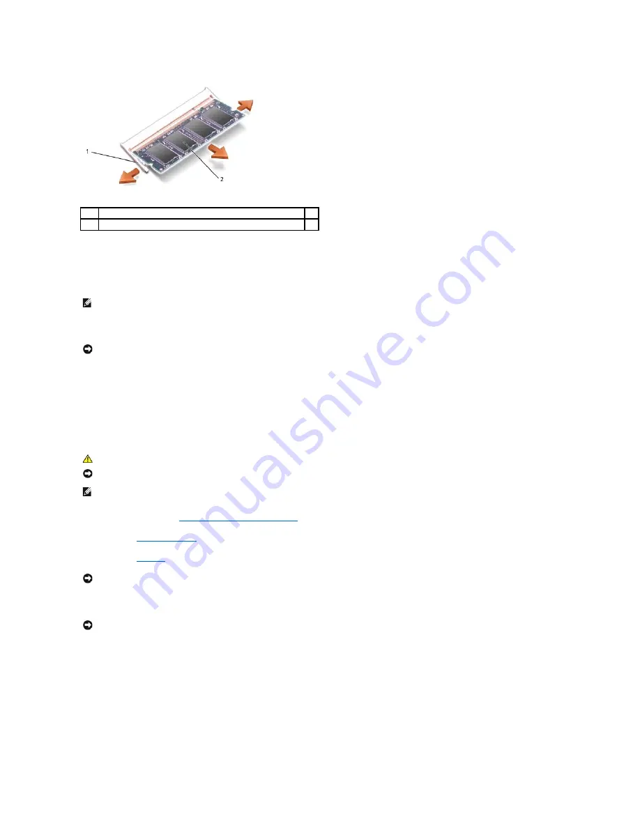
Use your fingertips to carefully spread apart the securing clips on each end of the memory module connector until the module pops up.
b.
Remove the module from the connector.
1
securing clips (2 per connector)
2
memory module
NOTE:
If the memory module is not installed properly, the computer does not boot. The Num Lock and Scroll Lock lights blink about 10 times.
NOTICE:
If the memory module cover is difficult to close, remove the module and reinstall it. Forcing the cover to close may damage your computer.
CAUTION:
Before working inside your Dell™ computer, read the safety instructions in your
Product Information Guide
.
NOTICE:
To prevent static damage to components inside your computer, discharge static electricity from your body before you touch any of your
computer's electronic components. You can do so by touching an unpainted metal surface.
NOTE:
Memory modules purchased from Dell are covered under your computer warranty.
NOTICE:
To prevent damage to the memory module connector, do not use tools to spread the inner metal tabs that secure the memory module.
NOTICE:
Handle memory modules by their edges, and do not touch the components on a module.
Содержание Latitude D810
Страница 5: ...Back to Contents Page Internal card with Bluetooth wireless technology 1 each Button Board 2 each ...
Страница 25: ...Back to Contents Page ...
Страница 27: ...Back to Contents Page 1 M2 5 x 5 mm screws 2 2 keyboard 3 palm rest 4 keyboard tabs 5 ...
Страница 41: ...When replacing the thermal cooling assembly follow the steps in reverse order Back to Contents Page ...


