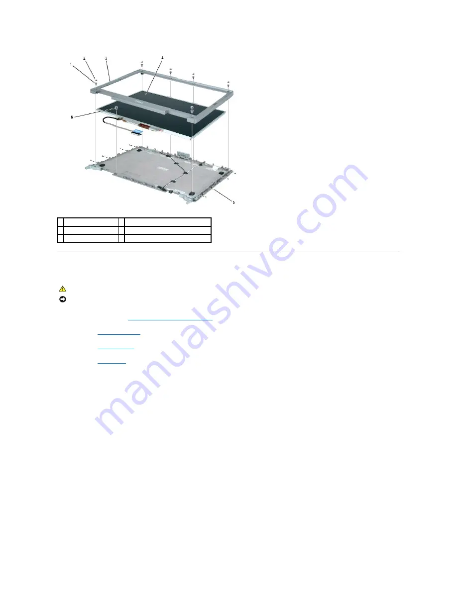
Display Panel
1.
Follow the instructions in "
Preparing to Work Inside the Computer
."
2.
Remove the
center control cover
.
3.
Remove the
display assembly
.
4.
Remove the
display bezel
.
Remove the eight M2 x 3-mm screws from sides of the display panel.
NOTE:
The M2 x 3-mm screw located in the top left of the panel should be removed first and reinstalled first.
6.
Remove the M2 x 3-mm screw for the display cable ground, which is located at the bottom of the display panel.
7.
Lift the display panel straight up out of the top cover.
8.
Press in the tabs on both sides of the top display-cable connector, and pull the display cable connector away from the top flex-cable connector.
NOTE:
Do not crimp or crunch cables during reinstallation.
1 M2.5 x 5-mm screws (6) 4 display panel
2 display bumpers (6)
5 M2 x 3-mm screws (8)
3 display bezel
6 M2 x 3-mm display-cable ground screw
CAUTION:
Before performing the following procedures, read the safety instructions in your
Product Information Guide
.
NOTICE:
To avoid electrostatic discharge, ground yourself by using a wrist grounding strap or by touching an unpainted metal surface on the computer.
Содержание Latitude D810
Страница 5: ...Back to Contents Page Internal card with Bluetooth wireless technology 1 each Button Board 2 each ...
Страница 25: ...Back to Contents Page ...
Страница 27: ...Back to Contents Page 1 M2 5 x 5 mm screws 2 2 keyboard 3 palm rest 4 keyboard tabs 5 ...
Страница 41: ...When replacing the thermal cooling assembly follow the steps in reverse order Back to Contents Page ...


