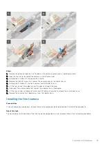
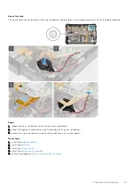

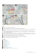
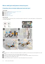


6. Flip the cables and lift the rubber grommet to release the DC-in and serial port from the system chassis.
NOTE:
Rubber grommet ensures to secure the micro serial port cable from damage.
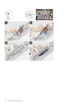
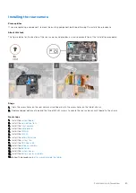
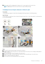
Installing micro serial port and power connector port
Prerequisites
If you are replacing a component, remove the existing component before performing the installation procedure.
About this task
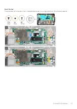
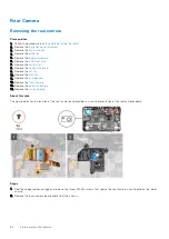
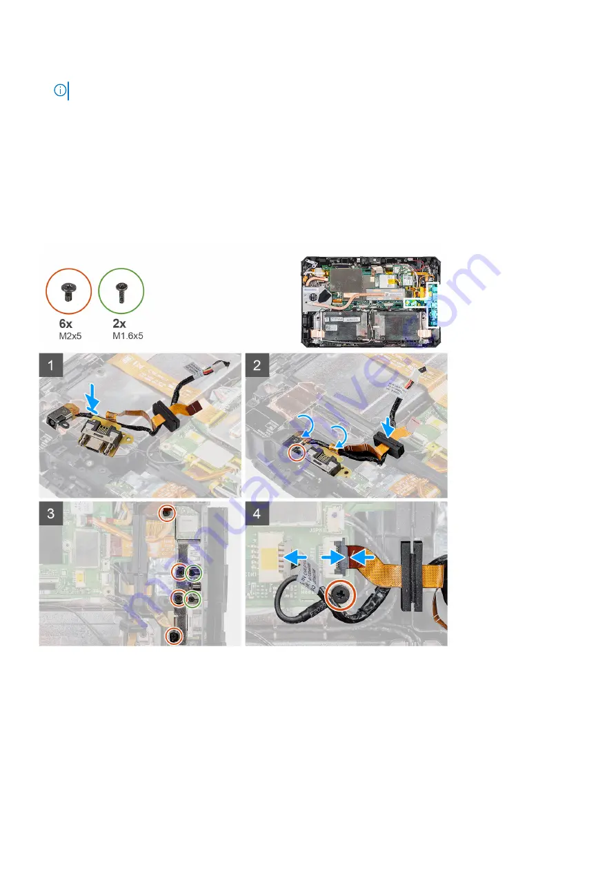
The figure indicates the location of the micro serial port and power connector (DC-in) port and provides a visual representation
of the installation procedure.
Steps
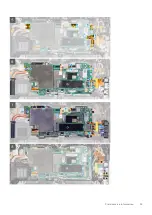
1. Insert the DC-in port and micro serial port into the slot on the chassis.
2. Replace the (M2x5) screw that secures the DC-in port and serial port to the system chassis and align the rubber grommet
to slide in the channel .
3. Align the metal brackets that secure the ports on the system chassis.
4. Replace the four (M2x5) screws and two (M1.6x5) screws that secure the metal bracket to the system chassis.
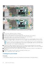
5. Connect the serial port cable into the connector.
6. Close the latch to secure the serial port cable to the system board.
Field service information
67
Содержание Latitude 7220EX
Страница 20: ...20 Field service information ...
Страница 22: ...22 Field service information ...
Страница 31: ...Field service information 31 ...
Страница 32: ...32 Field service information ...
Страница 35: ...Field service information 35 ...
Страница 36: ...36 Field service information ...
Страница 52: ...52 Field service information ...
Страница 54: ...54 Field service information ...
Страница 59: ...Field service information 59 ...
Страница 62: ...62 Field service information ...
Страница 83: ...3 The Bios flash menu will open then click the Flash from file 4 Select external USB device System setup 83 ...


