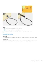
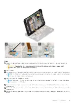
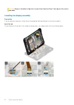
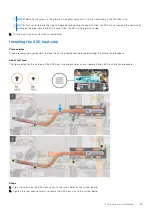
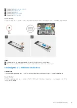
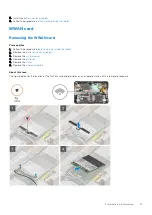
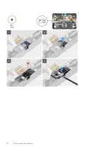
Steps
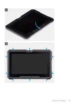
1. Place the LCD panel by less than 90°, use a plastic scribe to connect the eDP cable and close the latch. Secure the
connector with the attached adhesive tape that came with the eDP cable.
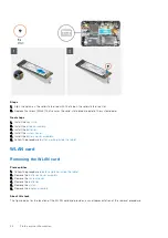
2. Using a plastic scribe, connect the function key cable to the connector on the system board and close the latch. Secure the
connector with new adhesive tape.
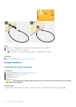
3. Using a plastic scribe, connect the touch cable to the connector on the system board and close the latch. Secure the
connector with new adhesive tape.
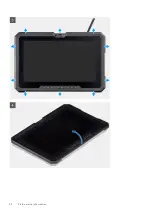
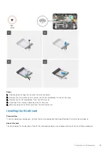
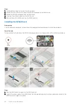
4. Align the LCD panel on the chassis.
5. Press the edges of the display assembly to secure it to the chassis.
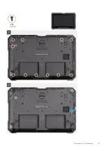
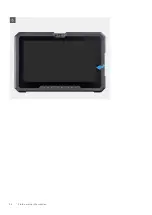
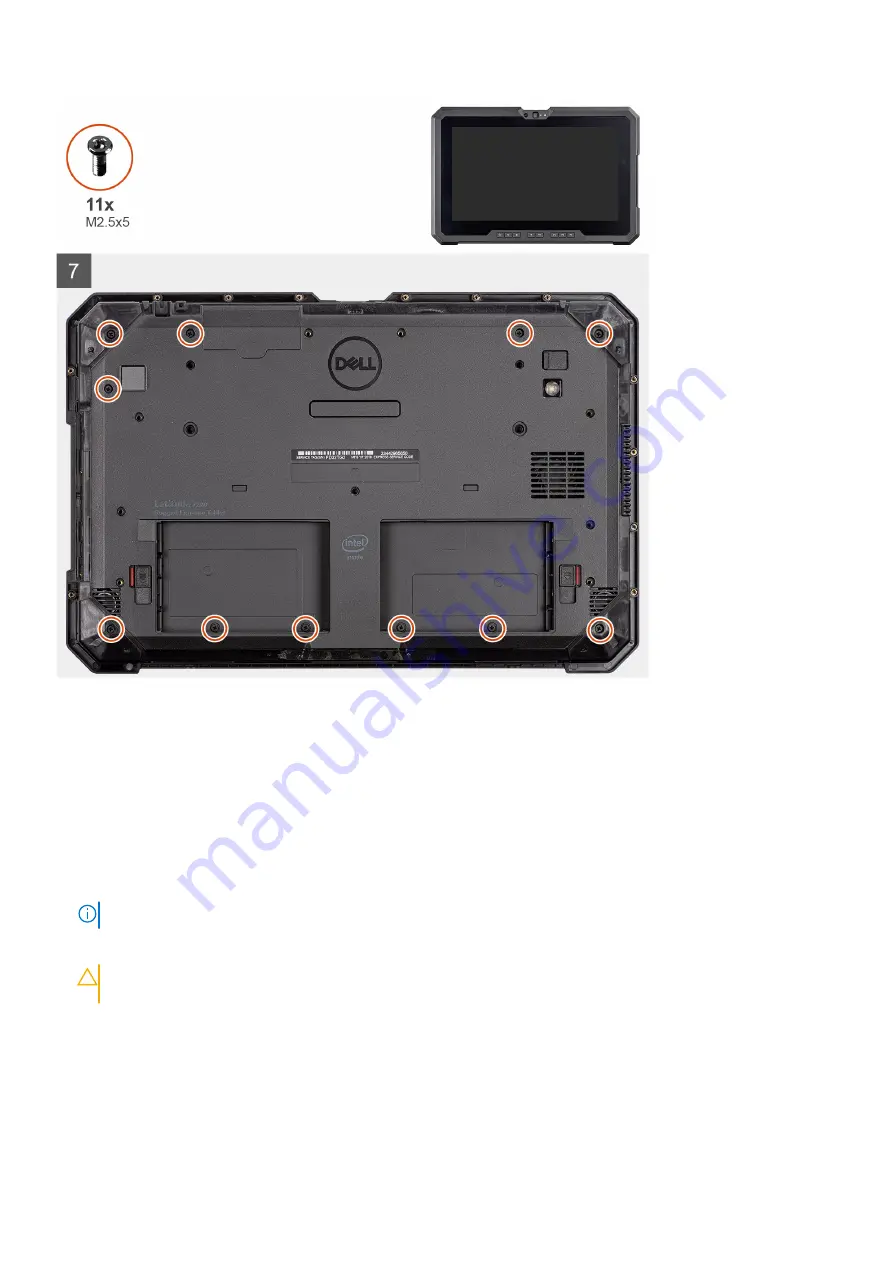
6. Flip the tablet.
NOTE:
Ensure to place the tablet on a flat surface.
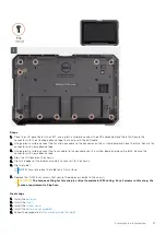
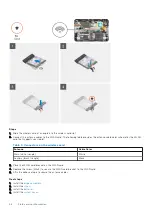
7. Replace the 11 (M2.5x5) screws that secure the display assembly to the chassis.
CAUTION:
The torque setting for this step is critical to maintain IP20 rating. For all screws in this step, the
torque requirement is 4 kgf-cm.
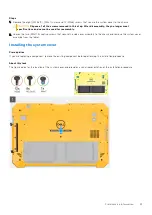
Next steps
1. Install the
.
2. Install the
3. Install the
.
4. Install the
.
after working inside the tablet
Field service information
37
Содержание Latitude 7220EX
Страница 20: ...20 Field service information ...
Страница 22: ...22 Field service information ...
Страница 31: ...Field service information 31 ...
Страница 32: ...32 Field service information ...
Страница 35: ...Field service information 35 ...
Страница 36: ...36 Field service information ...
Страница 52: ...52 Field service information ...
Страница 54: ...54 Field service information ...
Страница 59: ...Field service information 59 ...
Страница 62: ...62 Field service information ...
Страница 83: ...3 The Bios flash menu will open then click the Flash from file 4 Select external USB device System setup 83 ...


