888-24-116-W-00 rev.A • 05/10
1
2
3
4
5
6
8
7
12
13
15
14
10
11
9
ENGLISH
3 / 32
Dell Mobile Computing Station 2.0
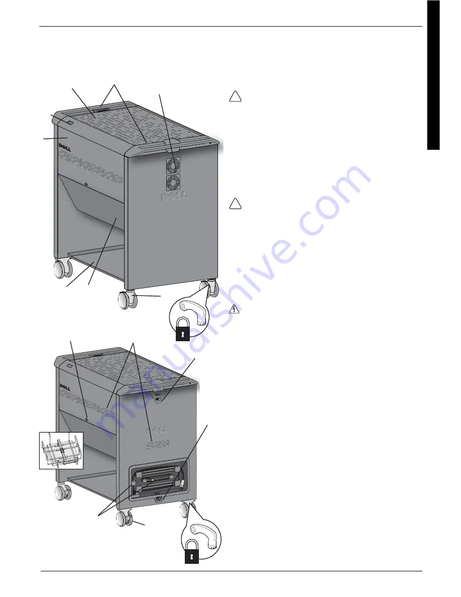
1
Retractable Doors (upper compartment)
• The upper doors stow under the work surface for unobstructed
access to the Netbooks without changing the MCS footprint.
When closed, the upper doors overlap the lower doors and conceal
the lower compartment locks.
CAUTION:
Keep the doors locked when the MCS is unattended or
in transit.
2
Power/Fault Status Indicator
• Displays the MCS fault and power indicators.
3
Work Surface With Anti-static Mat
• The maximum weight capacity of the work surface is 25 lb (11.4 kg).
4
Ergonomic Handles
• Positioned at each end of the MCS for optimum comfort and
maneuverability.
5
Fan Guards
• Allow air fl ow and off er protection from fan blades.
CAUTION:
Do not block fan or vent openings. To prevent
overheating, leave 5-inches (127 mm) or more clearance
around fan and vent openings.
6
Keyed, Rotating Front Casters
• The 4-inch (101 mm) rotating casters make steering and moving
over thresholds easier; the casters can be locked to prevent rolling; 2
keys are provided for the brake lock feature.
7
Locking, Hinged Doors (Lower Compartment)
• When closed, the AC Adapters and Controller Box are
concealed from view.
• The Risk of Shock label on the door alerts adults to prohibit children
from opening the lower compartments.
ELECTRICAL:
Always disconnect the MCS power cable from the
wall outlet before opening the lower compartments. Do not allow
children to open the lower compartments.
8
Lower Storage Shelf
• The maximum weight capacity of the lower shelf is 60 lb (27.2 kg).
9
Locks
• 4 locks: one on each upper compartment door, one on each lower
compartment door; all four locks open with the same key (4 keys are
provided).
10
Ventilation System
• The vents on the sides and back end of the MCS improve air fl ow; the
compartment contents are hidden from view.
11
Theft Deterrent Loops
• A heavy-duty loop is located near the handle above the cable bay.
12
MCS Security
• A heavy-duty loop is located near the recessed cable management
area to anchor the MCS to the wall or to the fl oor.
13
Keyed, Fixed Rear Casters
• The 4-inch (101 mm) fi xed casters make maneuvering the MCS easier.
• The casters can be locked to prevent rolling; 2 keys are provided for
the brake lock feature.
14
External Cable Management Bay
• Keeps the MCS power cable and Ethernet cable organized, protected
and close-at-hand; includes an 8-foot (2.4 m) power cable and 10-foot
(3 m) Ethernet cable.
15
Optional Wireless Access Point (WAP)
• Located beneath the lower compartments.
• The wire guard and strap hold the WAP securely, protecting it from
damage.
Exterior Features


