background image

32

  |  Memory 

Module(s)

3

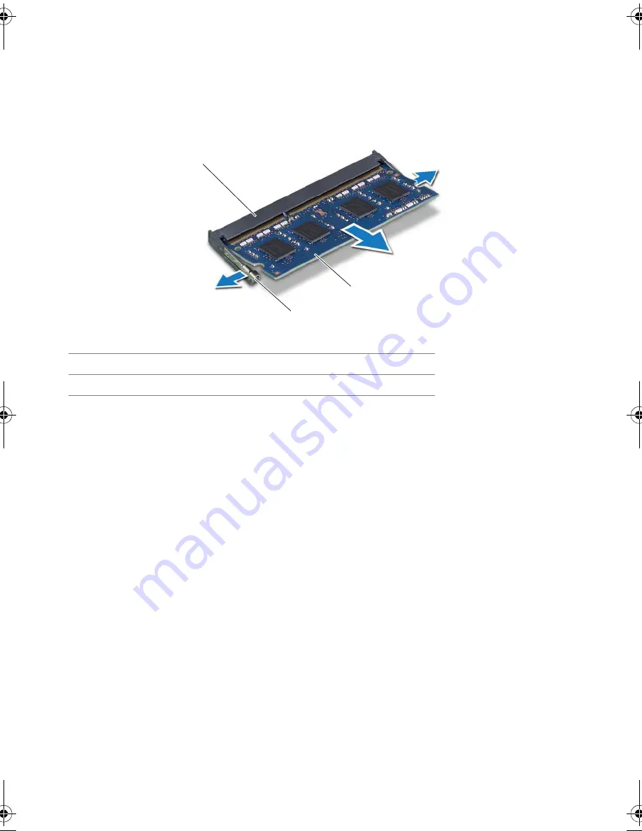
Use your fingertips to carefully spread apart the securing clips on each end of the 
memory-module connector until the memory module pops up. 

4

Remove the memory module from the memory-module connector. 

1

memory-module connector

2

securing clips (2)

3

memory  module

1

2

3

book.book  Page 32  Monday, April 16, 2012  3:04 PM

Содержание Inspiron One 2020

Страница 1: ...Dell Inspiron One 2020 Owner s Manual Computer model Inspiron One 2020 Regulatory model W06B Regulatory type W06B001 ...

Страница 2: ...c is strictly forbidden Trademarks used in this text Dell the DELL logo and Inspiron are trademarks of Dell Inc Microsoft Windows and the Windows start button logo are either trademarks or registered trademarks of Microsoft corporation in the United States and or other countries Intel and Intel SpeedStep are registered trademarks of Intel Corporation in the U S and other countries Bluetooth is a r...

Страница 3: ...omputer 13 4 Stand Cover 15 Removing the Stand Cover 15 Replacing the Stand Cover 16 5 Stand 17 Removing the Stand 17 Replacing the Stand 18 6 Back Cover 19 Removing the Back Cover 19 Replacing the Back Cover 20 7 Hard Drive 21 Removing the Hard Drive 21 Replacing the Hard Drive 23 8 Optical Drive 25 Removing the Optical Drive 25 Replacing the Optical Drive 26 9 B CAS Card Japan Only 27 Removing t...

Страница 4: ...nector 37 Replacing the Antenna In Connector 38 14 Antenna Modules 39 Removing the Antenna Modules 39 Replacing the Antenna Modules 40 15 TV Tuner Card Optional 41 Removing the TV Tuner Card 41 Replacing the TV Tuner Card 43 16 Wireless Mini Card Optional 45 Removing the Wireless Mini Card 45 Replacing the Wireless Mini Card 47 17 Coin Cell Battery 49 Removing the Coin Cell Battery 49 Replacing th...

Страница 5: ...ing the System Board 69 Replacing the System Board 71 Entering the Service Tag in the BIOS 71 24 Display Panel 73 Removing the Display Panel 73 Replacing the Display Panel 77 25 Infrared IR Receiver 79 Removing the Infrared Receiver 79 Replacing the Infrared Receiver 82 26 Middle Frame 83 Removing the Middle Frame 83 Replacing the Middle Frame 85 27 Camera Module 87 Removing the Camera Module 87 R...

Страница 6: ...6 Contents 29 System Setup 95 Overview 95 Clearing Forgotten Passwords 106 Clearing CMOS Settings 107 30 Flashing the BIOS 109 ...

Страница 7: ...st practices information see the Regulatory Compliance Homepage at dell com regulatory_compliance Inside View of Your Computer 1 power button board 2 chassis 3 optical drive assembly 4 converter board 5 fan 6 processor heat sink 7 memory module s 8 coin cell battery 9 system board 10 TV tuner card optional 11 wireless Mini Card 12 B CAS card Japan only 13 hard drive assembly 14 speakers 2 1 2 3 4 ...

Страница 8: ...8 Technical Overview System Board Components 1 2 3 4 5 6 7 8 9 10 11 12 13 15 17 18 14 16 ...

Страница 9: ...ctor SATA_ODD 7 hard drive cable connector SATA_HDD 8 power button and hard drive activity light cable connector PWRCN1 9 IR cable connector IR_IN 10 display cable connector 11 wireless Mini Card connector MINICARD WIFI 12 TV tuner card connector MINICARD TV 13 speakers cable connector SPEAKER 14 password jumper PWCLR1 15 battery socket BT1 16 CMOS jumper CMOCL1 17 memory module connector DIMMB1 1...

Страница 10: ...10 Technical Overview ...

Страница 11: ...e safety information that shipped with your computer For additional safety best practices information see the Regulatory Compliance Homepage at dell com regulatory_compliance WARNING Disconnect all power sources before opening the computer cover or panels After you finish working inside the computer replace all covers panels and screws before connecting to the power source CAUTION To avoid damagin...

Страница 12: ...en disconnecting cables keep them evenly aligned to avoid bending any connector pins When connecting cables ensure that the connectors and ports are correctly oriented and aligned CAUTION To disconnect a network cable first unplug the cable from your computer and then unplug the cable from the network device Recommended Tools The procedures in this document may require the following tools Phillips...

Страница 13: ...ide your computer Place the computer in an upright position Connect any external devices cables cards and any other part s you removed before working on your computer Connect your computer and all attached devices to their electrical outlets CAUTION Before turning on your computer replace all screws and ensure that no stray screws remain inside the computer Failure to do so may damage your compute...

Страница 14: ...14 After Working Inside Your Computer ...

Страница 15: ...gulatory Compliance Homepage at dell com regulatory_compliance Removing the Stand Cover Procedure CAUTION Before opening your computer ensure that you place the computer on a soft cloth or clean surface to avoid any scratches on the display 1 Place the computer face down on a flat surface 2 Press the tab on the stand cover and lift the stand cover 3 Slide and remove the stand cover away from the c...

Страница 16: ...ing the Stand Cover Procedure 1 Slide the tabs on the stand cover into the slots on the back cover 2 Snap the stand cover until it clicks into place 3 Follow the instructions in After Working Inside Your Computer on page 13 ...

Страница 17: ...11 For additional safety best practices information see the Regulatory Compliance Homepage at dell com regulatory_compliance Removing the Stand Prerequisites Remove the stand cover See Removing the Stand Cover on page 15 Procedure 1 Remove the screws that secure the stand to the chassis 2 Pivot the stand upward and slide it away from the computer 1 stand 2 screws 4 2 1 ...

Страница 18: ...n the stand into the slots on the back cover 2 Replace the screws that secure the stand to the chassis Postrequisites 1 Replace the stand cover See Replacing the Stand Cover on page 16 2 Follow the instructions in After Working Inside Your Computer on page 13 ...

Страница 19: ...practices information see the Regulatory Compliance Homepage at dell com regulatory_compliance Removing the Back Cover Prerequisites 1 Remove the stand cover See Removing the Stand Cover on page 15 2 Remove the stand See Removing the Stand on page 17 Procedure 1 Starting from above the optical drive pry the back cover from the middle frame 2 Lift the back cover off the computer 1 middle frame 2 ba...

Страница 20: ...r with the tabs on the middle frame and snap the back cover into place Postrequisites 1 Replace the stand See Replacing the Stand on page 18 2 Replace the stand cover See Replacing the Stand Cover on page 16 3 Follow the instructions in After Working Inside Your Computer on page 13 ...

Страница 21: ...mpliance Homepage at dell com regulatory_compliance CAUTION To avoid data loss do not remove the hard drive while the computer is On or in Sleep state CAUTION Hard drives are extremely fragile Exercise care when handling the hard drive Removing the Hard Drive Prerequisites 1 Remove the stand cover See Removing the Stand Cover on page 15 2 Remove the stand See Removing the Stand on page 17 3 Remove...

Страница 22: ... assembly and then disconnect the power and data cable from the connector on the hard drive 3 Remove the screws that secure the hard drive cage to the hard drive 4 Lift the hard drive cage off the hard drive 1 chassis 2 screw 3 3 hard drive assembly 4 power and data cable 1 hard drive cage 2 hard drive 3 screws 4 2 3 4 1 1 2 3 ...

Страница 23: ...ve assembly on the chassis and slide the hard drive assembly into place Ensure that the slots on the hard drive cage are secured under the tabs on the chassis 5 Replace the screws that secure the hard drive assembly to the chassis Postrequisites 1 Replace the back cover See Replacing the Back Cover on page 20 2 Replace the stand See Replacing the Stand on page 18 3 Replace the stand cover See Repl...

Страница 24: ...24 Hard Drive ...

Страница 25: ...oving the Optical Drive Prerequisites 1 Remove the stand cover See Removing the Stand Cover on page 15 2 Remove the stand See Removing the Stand on page 17 3 Remove the back cover See Removing the Back Cover on page 19 Procedure 1 Disconnect the power and data cable from the connector on the optical drive assembly 2 Remove the screw that secures the optical drive assembly to the chassis 3 Slide th...

Страница 26: ...e slots on the optical drive assembly and snap the optical drive bezel into place 4 Slide the optical drive assembly into the optical drive bay until it is fully seated 5 Replace the screw that secures the optical drive assembly to the chassis 6 Connect the power and data cable to the connector on the optical drive assembly Postrequisites 1 Replace the back cover See Replacing the Back Cover on pa...

Страница 27: ...ry_compliance Removing the B CAS Card Prerequisites 1 Remove the stand cover See Removing the Stand Cover on page 15 2 Remove the stand See Removing the Stand on page 17 3 Remove the back cover See Removing the Back Cover on page 19 Procedure 1 Remove the screw that secures the B CAS card to the middle frame 2 Turn the B CAS card over 3 Disconnect the B CAS card cable from the connector on the B C...

Страница 28: ... card with the screw hole on the middle frame 4 Replace the screw that secures the B CAS card to the middle frame Postrequisites 1 Replace the back cover See Replacing the Back Cover on page 20 2 Replace the stand See Replacing the Stand on page 18 3 Replace the stand cover See Replacing the Stand Cover on page 16 4 Follow the instructions in After Working Inside Your Computer on page 13 ...

Страница 29: ...l com regulatory_compliance Removing the Converter Board Prerequisites 1 Remove the stand cover See Removing the Stand Cover on page 15 2 Remove the stand See Removing the Stand on page 17 3 Remove the back cover See Removing the Back Cover on page 19 Procedure 1 Disconnect the cables from the connectors on the converter board 2 Remove the screws that secure the converter board to the chassis 3 Li...

Страница 30: ...e the converter board to the chassis 3 Connect the cables to the connectors on the converter board Postrequisites 1 Replace the back cover See Replacing the Back Cover on page 20 2 Replace the stand See Replacing the Stand on page 18 3 Replace the stand cover See Replacing the Stand Cover on page 16 4 Follow the instructions in After Working Inside Your Computer on page 13 ...

Страница 31: ...ulatory_compliance Removing the Memory Module s Prerequisites 1 Remove the stand cover See Removing the Stand Cover on page 15 2 Remove the stand See Removing the Stand on page 17 3 Remove the back cover See Removing the Back Cover on page 19 Procedure 1 Remove the screw that secures the memory module shield to the system board shield 2 Slide the memory module shield toward the top of the computer...

Страница 32: ... carefully spread apart the securing clips on each end of the memory module connector until the memory module pops up 4 Remove the memory module from the memory module connector 1 memory module connector 2 securing clips 2 3 memory module 1 2 3 ...

Страница 33: ...d toward the bottom of the computer Ensure that the screw hole on the memory module shield aligns with the screw hole on the system board shield 4 Replace the screw that secures the memory module shield to the system board shield Postrequisites 1 Replace the back cover See Replacing the Back Cover on page 20 2 Replace the stand See Replacing the Stand on page 18 3 Replace the stand cover See Repla...

Страница 34: ...34 Memory Module s ...

Страница 35: ...latory Compliance Homepage at dell com regulatory_compliance Removing the System Board Shield Prerequisites 1 Remove the stand cover See Removing the Stand Cover on page 15 2 Remove the stand See Removing the Stand on page 17 3 Remove the back cover See Removing the Back Cover on page 19 Procedure 1 Remove the screws that secure the system board shield to the chassis 2 Carefully lift the system bo...

Страница 36: ...ector on the TV tuner card 3 Turn the system board shield over and align the screw holes on the system board shield with the screw holes on the chassis 4 Replace the screws that secure the system board shield to the chassis Postrequisites 1 Replace the back cover See Replacing the Back Cover on page 20 2 Replace the stand See Replacing the Stand on page 18 3 Replace the stand cover See Replacing t...

Страница 37: ...uisites 1 Remove the stand cover See Removing the Stand Cover on page 15 2 Remove the stand See Removing the Stand on page 17 3 Remove the back cover See Removing the Back Cover on page 19 4 Remove the system board shield See Removing the System Board Shield on page 35 Procedure 1 Remove the hex nut that secures the antenna in connector to the system board shield 2 Slide the antenna in connector t...

Страница 38: ...onnector to the system board shield Postrequisites 1 Replace the system board shield See Replacing the System Board Shield on page 36 2 Replace the back cover See Replacing the Back Cover on page 20 3 Replace the stand See Replacing the Stand on page 18 4 Replace the stand cover See Replacing the Stand Cover on page 16 5 Follow the instructions in After Working Inside Your Computer on page 13 ...

Страница 39: ...quisites 1 Remove the stand cover See Removing the Stand Cover on page 15 2 Remove the stand See Removing the Stand on page 17 3 Remove the back cover See Removing the Back Cover on page 19 4 Remove the system board shield See Removing the System Board Shield on page 35 Procedure 1 Disconnect the antenna cables from the connectors on the wireless Mini Card 2 Make a note of the antenna cables routi...

Страница 40: ...onnectors on the wireless Mini Card Postrequisites 1 Replace the system board shield See Replacing the System Board Shield on page 36 2 Replace the back cover See Replacing the Back Cover on page 20 3 Replace the stand See Replacing the Stand on page 18 4 Replace the stand cover See Replacing the Stand Cover on page 16 5 Follow the instructions in After Working Inside Your Computer on page 13 ...

Страница 41: ...ot guarantee compatibility or provide support for TV tuner cards from sources other than Dell If you ordered a TV tuner card with your computer the card is already installed Your computer supports one full size Mini Card slot for a TV tuner card Removing the TV Tuner Card Prerequisites 1 Remove the stand cover See Removing the Stand Cover on page 15 2 Remove the stand See Removing the Stand on pag...

Страница 42: ...ner card to the system board connector 3 Lift the TV tuner card away from the system board connector CAUTION When the TV tuner card is not in the computer store it in protective antistatic packaging See Protecting Against Electrostatic Discharge in the safety instructions that shipped with your computer 1 TV tuner card cable 2 screw 3 TV tuner card 1 2 3 ...

Страница 43: ... end of the TV tuner card down and replace the screw that secures the TV tuner card to the system board connector 4 Connect the TV tuner card cable to the connector on the TV tuner card Postrequisites 1 Replace the system board shield See Replacing the System Board Shield on page 36 2 Replace the back cover See Replacing the Back Cover on page 20 3 Replace the stand See Replacing the Stand on page...

Страница 44: ...44 TV Tuner Card Optional ...

Страница 45: ...lity or provide support for Mini Cards from sources other than Dell If you ordered a wireless Mini Card with your computer the card is already installed Your computer supports one half size Mini Card slot for Wireless Local Area Network WLAN Bluetooth combo card and Wi Fi Removing the Wireless Mini Card Prerequisites 1 Remove the stand cover See Removing the Stand Cover on page 15 2 Remove the sta...

Страница 46: ...ard to the system board connector 3 Lift the Mini Card away from the system board connector CAUTION When the Mini Card is not in the computer store it in protective antistatic packaging See Protecting Against Electrostatic Discharge in the safety instructions that shipped with your computer 1 screw 2 Mini Card 3 antenna cables 2 1 2 3 ...

Страница 47: ...hat secures the Mini Card to the system board connector 4 Connect the appropriate antenna cables to the Mini Card you are installing The Mini Card has two triangles black and white marked on the label Connect the black cable to the connector marked with a black triangle Connect the white cable to the connector marked with a white triangle Postrequisites 1 Replace the system board shield See Replac...

Страница 48: ...48 Wireless Mini Card Optional ...

Страница 49: ...card used batteries according to the manufacturer s instructions Removing the Coin Cell Battery Prerequisites 1 Remove the stand cover See Removing the Stand Cover on page 15 2 Remove the stand See Removing the Stand on page 17 3 Remove the back cover See Removing the Back Cover on page 19 4 Remove the system board shield See Removing the System Board Shield on page 35 Procedure 1 Locate the batte...

Страница 50: ... into place Postrequisites 1 Replace the system board shield See Replacing the System Board Shield on page 36 2 Replace the back cover See Replacing the Back Cover on page 20 3 Replace the stand See Replacing the Stand on page 18 4 Replace the stand cover See Replacing the Stand Cover on page 16 5 Follow the instructions in After Working Inside Your Computer on page 13 ...

Страница 51: ...ee the Regulatory Compliance Homepage at dell com regulatory_compliance Removing the Speakers Prerequisites 1 Remove the stand cover See Removing the Stand Cover on page 15 2 Remove the stand See Removing the Stand on page 17 3 Remove the back cover See Removing the Back Cover on page 19 4 Remove the B CAS card See Removing the B CAS Card on page 27 5 Remove the system board shield See Removing th...

Страница 52: ...system board 2 Make note of the speakers cable routing and remove the cable from the routing guides 3 Remove the screws that secure the speakers to the middle frame 4 Lift the speakers along with the cable off the middle frame 1 screws 4 2 speakers 2 3 middle frame 4 speakers cable 1 2 4 3 ...

Страница 53: ...ble to the connector SPEAKER on the system board Postrequisites 1 Replace the system board shield See Replacing the System Board Shield on page 36 2 Replace the B CAS card See Replacing the B CAS Card on page 28 3 Replace the back cover See Replacing the Back Cover on page 20 4 Replace the stand See Replacing the Stand on page 18 5 Replace the stand cover See Replacing the Stand Cover on page 16 6...

Страница 54: ...54 Speakers ...

Страница 55: ... best practices information see the Regulatory Compliance Homepage at dell com regulatory_compliance Removing the Fan Prerequisites 1 Remove the stand cover See Removing the Stand Cover on page 15 2 Remove the stand See Removing the Stand on page 17 3 Remove the back cover See Removing the Back Cover on page 19 4 Remove the system board shield See Removing the System Board Shield on page 35 ...

Страница 56: ...e the screws that secure the fan to the chassis 3 Route the fan cable through the routing guide on the fan 4 Connect the fan cable to the connector FANC1 on the system board Postrequisites 1 Replace the system board shield See Replacing the System Board Shield on page 36 2 Replace the back cover See Replacing the Back Cover on page 20 3 Replace the stand See Replacing the Stand on page 18 4 Replac...

Страница 57: ...al safety best practices information see the Regulatory Compliance Homepage at dell com regulatory_compliance Removing the Power Button Assembly Prerequisites 1 Remove the stand cover See Removing the Stand Cover on page 15 2 Remove the stand See Removing the Stand on page 17 3 Remove the back cover See Removing the Back Cover on page 19 4 Remove the system board shield See Removing the System Boa...

Страница 58: ...power button and hard drive activity light cable routing and remove it from the routing guides 3 Remove the screw that secures the power button assembly to the middle frame 4 Slide the power button assembly toward the top of the computer and then lift it away from the middle frame 1 screw 2 power button assembly 3 power button and hard drive activity light cable 1 2 3 ...

Страница 59: ...he power button assembly to the middle frame 4 Route the power button and hard drive activity light cable through the routing guides 5 Connect the power button and hard drive activity light cable to the connector PWRCN1 on the system board Postrequisites 1 Replace the system board shield See Replacing the System Board Shield on page 36 2 Replace the back cover See Replacing the Back Cover on page ...

Страница 60: ...60 Power Button Assembly ...

Страница 61: ...ation Ensure that it has had sufficient time to cool before you touch it Removing the Processor Heat Sink CAUTION To ensure maximum cooling for the processor do not touch the heat transfer areas on the processor heat sink The oils in your skin can reduce the heat transfer capability of the thermal grease Prerequisites 1 Remove the stand cover See Removing the Stand Cover on page 15 2 Remove the st...

Страница 62: ...t sink loosen the captive screws that secure the processor heat sink to the system board 2 Carefully lift the processor heat sink away from the system board NOTE The appearance of the processor heat sink may vary based on your computer model 1 processor heat sink 2 captive screws 7 1 2 ...

Страница 63: ...e provided in the kit to ensure that thermal conductivity is achieved 2 Align the captive screws on the processor heat sink with the screw holes on the system board 3 In sequential order indicated on the processor heat sink tighten the captive screws that secure the processor heat sink to the system board Postrequisites 1 Replace the system board shield See Replacing the System Board Shield on pag...

Страница 64: ...64 Processor Heat Sink ...

Страница 65: ...gulatory Compliance Homepage at dell com regulatory_compliance Removing the Processor Prerequisites 1 Remove the stand cover See Removing the Stand Cover on page 15 2 Remove the stand See Removing the Stand on page 17 3 Remove the back cover See Removing the Back Cover on page 19 4 Remove the system board shield See Removing the System Board Shield on page 35 5 Remove the processor heat sink See R...

Страница 66: ...he tab that secures it 2 Extend the release lever completely to open the processor cover Leave the release lever extended in the release position so that the socket is ready for the new processor 3 Gently lift the processor to remove it from the socket 1 release lever 2 tab 3 processor cover 4 socket 5 processor 1 2 3 5 4 ...

Страница 67: ...anent damage to the processor 3 Orient the alignment notches on the processor with the alignment tabs on the socket 4 Align the pin 1 corners of the processor and socket CAUTION Ensure that the processor cover notch is positioned underneath the alignment post 5 When the processor is fully seated in the socket close the processor cover 6 Pivot the release lever down and place it under the tab on th...

Страница 68: ...ment for optimal processor operation Postrequisites 1 Replace the processor heat sink See Replacing the Processor Heat Sink on page 63 2 Replace the system board shield See Replacing the System Board Shield on page 36 3 Replace the back cover See Replacing the Back Cover on page 20 4 Replace the stand See Replacing the Stand on page 18 5 Replace the stand cover See Replacing the Stand Cover on pag...

Страница 69: ... Stand Cover on page 15 2 Remove the stand See Removing the Stand on page 17 3 Remove the back cover See Removing the Back Cover on page 19 4 Remove the system board shield See Removing the System Board Shield on page 35 5 Remove the memory module s See Removing the Memory Module s on page 31 6 Remove the wireless Mini Card See Removing the Wireless Mini Card on page 45 7 Remove TV tuner card if a...

Страница 70: ... Service Tag in the BIOS after you replace the system board 1 Disconnect all the cables from their connectors on the system board 2 Remove the screws that secure the system board to the chassis 3 Lift the system board at an angle and then slide it to release the connectors on the system board from the slots on the chassis 4 Remove the system board away from the chassis 1 system board 2 screws 5 1 ...

Страница 71: ...Replacing the TV Tuner Card on page 43 4 Replace the wireless Mini Card See Replacing the Wireless Mini Card on page 47 5 Replace the memory module s See Replacing the Memory Module s on page 33 6 Replace the system board shield See Replacing the System Board Shield on page 36 7 Replace the back cover See Replacing the Back Cover on page 20 8 Replace the stand See Replacing the Stand on page 18 9 ...

Страница 72: ...72 System Board ...

Страница 73: ...ng the Stand Cover on page 15 2 Remove the stand See Removing the Stand on page 17 3 Remove the back cover See Removing the Back Cover on page 19 4 Follow the instructions from step 1 to step 3 in Removing the Optical Drive on page 25 5 Follow the instructions from step 1 to step 2 in Removing the Hard Drive on page 21 6 Remove the converter board See Removing the Converter Board on page 29 7 Remo...

Страница 74: ... board cable and antenna cables and remove them from the routing guides on the chassis 2 Remove the screws that secure the chassis to the middle frame 3 Lift the chassis along with the display panel off the middle frame and place it on a clean surface 1 middle frame 2 chassis 3 screws 13 3 2 1 ...

Страница 75: ...converter board cable from the connector on the display panel 5 Remove the screws that secure the display panel to the chassis 6 Lift the chassis off the display panel 1 converter board cable 2 screws 4 1 chassis 2 display panel 2 1 1 2 ...

Страница 76: ...ble to the display cable connector 8 Press the release latch on either side of the display cable and then pull the display cable to disconnect it from the display cable connector 1 display cable 2 display panel 3 release latches 2 4 display cable connector 5 tape 1 2 3 4 5 ...

Страница 77: ...ng guides on the chassis Postrequisites 1 Replace the system board See Replacing the System Board on page 71 2 Replace the system board shield See Replacing the System Board Shield on page 36 3 Replace the fan See Replacing the Fan on page 56 4 Replace the converter board See Replacing the Converter Board on page 30 5 Follow the instructions from step 3 to step 5 in Replacing the Hard Drive on pag...

Страница 78: ...78 Display Panel ...

Страница 79: ...ee Removing the Stand Cover on page 15 2 Remove the stand See Removing the Stand on page 17 3 Remove the back cover See Removing the Back Cover on page 19 4 Follow the instructions from step 1 to step 3 in Removing the Optical Drive on page 25 5 Follow the instructions from step 1 to step 2 in Removing the Hard Drive on page 21 6 Remove the converter board See Removing the Converter Board on page ...

Страница 80: ...rter board cable and antenna cables and remove them from the routing guides on the chassis 2 Remove the screws that secure the chassis to the middle frame 3 Lift the chassis along with the display panel off the middle frame and keep it on a clean surface 1 middle frame 2 chassis 3 screws 13 3 2 1 ...

Страница 81: ...Infrared IR Receiver 81 4 Push the tabs that secure the IR receiver outward and remove the IR receiver from the display bezel 1 tabs 2 2 IR receiver 3 display bezel 1 2 3 ...

Страница 82: ...71 2 Replace the system board shield See Replacing the System Board Shield on page 36 3 Replace the fan See Replacing the Fan on page 56 4 Replace the converter board See Replacing the Converter Board on page 30 5 Follow the instructions from step 3 to step 5 in Replacing the Hard Drive on page 23 6 Follow the instructions from step 4 to step 6 in Replacing the Optical Drive on page 26 7 Replace t...

Страница 83: ...n page 19 4 Remove the B CAS card See Removing the B CAS Card on page 27 5 Remove the speakers See Removing the Speakers on page 51 6 Follow the instructions from step 1 to step 3 in Removing the Optical Drive on page 25 7 Follow the instructions from step 1 to step 2 in Removing the Hard Drive on page 21 8 Remove the converter board See Removing the Converter Board on page 29 9 Remove the fan See...

Страница 84: ...84 Middle Frame Procedure 1 Release the tabs that secure the middle frame to the display bezel 2 Lift the middle frame off the display bezel 1 middle frame 2 tabs 2 1 ...

Страница 85: ...the fan See Replacing the Fan on page 56 6 Replace the converter board See Replacing the Converter Board on page 30 7 Follow the instructions from step 3 to step 5 in Replacing the Hard Drive on page 23 8 Follow the instructions from step 4 to step 6 in Replacing the Optical Drive on page 26 9 Replace the speakers See Replacing the Speakers on page 53 10 Replace the B CAS card See Replacing the B ...

Страница 86: ...86 Middle Frame ...

Страница 87: ...nd on page 17 3 Remove the back cover See Removing the Back Cover on page 19 4 Follow the instructions from step 1 to step 3 in Removing the Optical Drive on page 25 5 Follow the instructions from step 1 to step 2 in Removing the Hard Drive on page 21 6 Remove the converter board See Removing the Converter Board on page 29 7 Remove the fan See Removing the Fan on page 55 8 Remove the system board ...

Страница 88: ...ra assembly along with its cable away from the display bezel 3 Remove the screw that secures the camera module to the camera module bracket 4 Slide and remove the camera module away from the camera module bracket 1 display bezel 2 camera assembly 3 screws 2 1 camera module bracket 2 camera module 3 screw 1 2 3 3 1 2 ...

Страница 89: ...See Replacing the Display Panel on page 77 3 Replace the system board See Replacing the System Board on page 71 4 Replace the system board shield See Replacing the System Board Shield on page 36 5 Replace the fan See Replacing the Fan on page 56 6 Replace the converter board See Replacing the Converter Board on page 30 7 Follow the instructions from step 3 to step 5 in Replacing the Hard Drive on ...

Страница 90: ...90 Camera Module ...

Страница 91: ...19 4 Follow the instructions from step 1 to step 3 in Removing the Optical Drive on page 25 5 Follow the instructions from step 1 to step 2 in Removing the Hard Drive on page 21 6 Remove the converter board See Removing the Converter Board on page 29 7 Remove the fan See Removing the Fan on page 55 8 Remove the system board shield See Removing the System Board Shield on page 35 9 Remove the system...

Страница 92: ...92 Display Bezel Procedure Remove the display bezel 1 display bezel 1 ...

Страница 93: ...on page 71 6 Replace the system board shield See Replacing the System Board Shield on page 36 7 Replace the fan See Replacing the Fan on page 56 8 Replace the converter board See Replacing the Converter Board on page 30 9 Follow the instructions from step 3 to step 5 in Replacing the Hard Drive on page 23 10 Follow the instructions from step 4 to step 6 in Replacing the Optical Drive on page 26 11...

Страница 94: ...94 Display Bezel ...

Страница 95: ...ectly NOTE Before you change system setup it is recommended that you write down the system setup screen information for future reference Entering System Setup 1 Turn on or restart your computer 2 During POST when the DELL logo is displayed watch for the F2 prompt to appear and then press F2 immediately NOTE The F2 prompt indicates that the keyboard has initialized This prompt can appear very quick...

Страница 96: ...st with the up and down arrow keys As an option is highlighted the Help Screen displays more information about that option and available settings Help Screen This field appears on the right side of the system setup window and contains information about each option listed in the Setup Item In this field you can view information about your computer and make changes to your current settings Press the...

Страница 97: ...uter Service Tag Input Allows you to enter the Service Tag of the computer if the Service Tag field is empty Asset Tag Displays the asset tag of the computer when the asset tag is present Main Processor Information Processor Type Displays the processor type Processor ID Displays the processor ID Processor Core Count Displays the number of core s Processor L1 Cache Displays the processor L1 cache s...

Страница 98: ...rial number of the SATA 1 device Device Size Displays the size of the SATA 1 device in GB if the device is a hard drive SATA 2 Device Type Displays the SATA device connected to the SATA 2 connector Device ID Displays the serial number of the SATA 2 device Device Size Displays the size of the SATA 2 device in GB if the device is a hard drive ...

Страница 99: ...or Enabled or Disabled Enabled by default CPU XD Support Allows you to enable or disable the execute disable mode for the processor Enabled or Disabled Enabled by default Limit CPUID Value Allows you to limit the maximum value the processor standard CPUID function supports Enabled or Disabled Disabled by default Multi Core Support Allows you to enable or disable multi core processor Enabled or Dis...

Страница 100: ...dvanced Onboard Device Configuration Onboard Audio Controller Allows you to enable or disable the onboard audio controller Enabled or Disabled Enabled by default SATA Mode Displays the SATA mode on your computer ATA by default Onboard LAN Controller Allows you to enable or disable the onboard LAN controller Enabled or Disabled Enabled by default Onboard LAN Boot ROM Allows you to boot your compute...

Страница 101: ... key and so on Enable or Disable Enabled by default Boot Mode Allows you to choose a boot mode for your computer Legacy or UEFI Legacy by default 1st Boot Device Displays the first boot device 2nd Boot Device Displays the second boot device 3rd Boot Device Displays the third boot device 4th Boot Device Displays the fourth boot device 5th Boot Device Displays the fifth boot device Hard Disk Drivers...

Страница 102: ...ed by default Auto Power On Mode Allows you to set the computer to turn on automatically every day or on a preselected date This option can be configured only if the Auto Power On mode is set to Enabled Everyday or Selected Day Selected Day by default Auto Power On Date Allows you to set the date on which the computer must turn on automatically This option can be configured only if the Auto Power ...

Страница 103: ...ows to set change or delete the supervisor password The supervisor password controls access to the system setup utility NOTE Deleting the supervisor password deletes the user password Set the supervisor password before setting the user password User Access Level Allows you to restrict or provide access to the system setup utility No Access View Only Limited or Full Access Full Access by default No...

Страница 104: ...nternal ODD Devices The computer attempts to boot from the optical drive If no disc is in the drive or if the disc is not bootable the computer generates an error message NOTE To boot to a USB device the device must be bootable To ensure that your device is bootable check the device documentation Onboard NIC Device The computer attempts to boot from the network If no operating system is found on t...

Страница 105: ...osoft Windows desktop Then shut down your computer and try again The Boot Device Menu appears listing all available boot devices 4 On the Boot Device Menu choose the device you want to boot from For example if you are booting to a USB memory key highlight USB Storage Device and press Enter NOTE To boot to a USB device the device must be bootable To ensure your device is bootable check the device d...

Страница 106: ...ing the Back Cover on page 19 4 Remove the system board shield See Removing the System Board Shield on page 35 5 Locate the 3 pin password reset jumper PWCLR1 on the system board See System Board Components on page 8 6 Remove the 2 pin jumper plug from pins 2 and 3 and fix it on pins 1 and 2 7 Wait for approximately five seconds to clear the password setting 8 Remove the 2 pin jumper plug from pin...

Страница 107: ...ng the Back Cover on page 19 4 Remove the system board shield See Removing the System Board Shield on page 35 5 Locate the 3 pin CMOS reset jumper CMOCL1 on the system board See System Board Components on page 8 6 Remove the 2 pin jumper plug from pins 2 and 3 and fix it on pins 1 and 2 7 Wait for approximately five seconds to clear the CMOS settings 8 Remove the 2 pin jumper plug from pins 1 and ...

Страница 108: ...108 System Setup ...

Страница 109: ...ve your computer s Service Tag or Express Service Code a Select one of the following options Automatically detect my Service Tag for me Choose from My Products and Services List Choose from a list of all Dell products b Click Continue and follow the instructions on the screen 4 A list of results appears on the screen Click BIOS 5 Click Download File to download the latest BIOS file 6 In the Please...

Страница 110: ...110 Flashing the BIOS ...

Отзывы: