background image

Steps

1. Lay the computer on the right side.
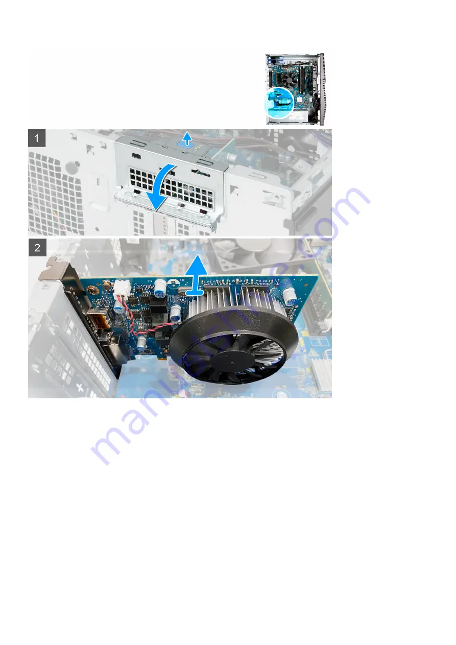
2. Locate the graphics card (PCI-Express).
3. Push the securing tabs on the graphics-card support bracket and rotate to remove it off the chassis.
4. Lift the pull tab to open the PCIE door.
5. Push and hold the securing tab on the graphics-card slot and lift the graphics card from the graphics-card slot.

Installing the graphics card

Prerequisites

If you are replacing a component, remove the existing component before performing the installation procedure.

About this task

The following images indicate the location of the graphics card and provides a visual representation of the installation procedure.

Removing and installing components

29

Содержание G5 5000

Страница 1: ...G5 5000 Service Manual Regulatory Model D28M Regulatory Type D28M003 June 2020 Rev A00 ...

Страница 2: ...ential damage to hardware or loss of data and tells you how to avoid the problem WARNING A WARNING indicates a potential for property damage personal injury or death 2020 Dell Inc or its subsidiaries All rights reserved Dell EMC and other trademarks are trademarks of Dell Inc or its subsidiaries Other trademarks may be trademarks of their respective owners ...

Страница 3: ...6 Chassis fan 17 Memory module 20 Wireless card 22 Solid state drive Intel Optane 24 Coin cell battery 27 Graphics card 28 Power button 30 Processor fan and heat sink assembly 32 Voltage regulator heat sink 34 Processor 36 Power supply unit 39 System board 42 Chapter 3 Drivers and downloads 51 Chapter 4 System setup 52 BIOS overview 52 Entering BIOS setup program 52 Navigation keys 52 One time boo...

Страница 4: ... diagnostic lights 60 Enabling Intel Optane memory 61 Disabling Intel Optane memory 61 Recovering the operating system 62 Flashing BIOS USB key 62 Flashing the BIOS 62 WiFi power cycle 63 Flea power release 63 Chapter 6 Getting help and contacting Dell 64 4 Contents ...

Страница 5: ...TION Before touching anything inside your computer ground yourself by touching an unpainted metal surface such as the metal at the back of the computer While you work periodically touch an unpainted metal surface to dissipate static electricity which could harm internal components CAUTION When you disconnect a cable pull it by its connector or its pull tab not the cable itself Some cables have con...

Страница 6: ...loor pads and workbench pads When unpacking a static sensitive component from its shipping carton do not remove the component from the anti static packing material until you are ready to install the component Before unwrapping the anti static packaging ensure that you discharge static electricity from your body Before transporting a static sensitive component place it in an anti static container o...

Страница 7: ...turned to Dell it is critical to place these parts in anti static bags for safe transport ESD protection summary It is recommended that all field service technicians use the traditional wired ESD grounding wrist strap and protective anti static mat at all times when servicing Dell products In addition it is critical that technicians keep sensitive parts separate from all insulator parts while perf...

Страница 8: ...mputers have magnetic surfaces Ensure that the screws are not left attached to such surface when replacing a component NOTE Screw color may vary with the configuration ordered Table 1 Screw list Component Secured to Screw type Quantity Screw image LED daughter board Chassis M2x3 1 3 5 inch hard drive assembly Chassis 6 32 1 3 5 inch hard drive Hard drive cage 6 32 4 Wireless card bracket System bo...

Страница 9: ...g image shows the major components of G5 5000 1 left side cover 2 coin cell battery 3 wireless card 4 chassis fan 5 M 2 2280 solid state drive 6 M 2 2230 solid state drive 7 power supply unit 8 processor fan and heat sink assembly 9 system board 10 front cover 11 LED daughter board 12 graphics card 13 memory module 14 processor 15 hard drive Removing and installing components 9 ...

Страница 10: ...t side cover and provides a visual representation of the removal procedure Steps 1 Loosen the two captive screws that secure the left side cover to the chassis 2 Using the tab on the left side cover slide and lift the left side cover off the chassis Installing the left side cover Prerequisites If you are replacing a component remove the existing component before performing the installation procedu...

Страница 11: ...r 2 Tighten the two captive screws that secure the left side cover to the chassis Next steps Follow the procedure in After working inside your computer Front cover Removing the front cover Prerequisites 1 Follow the procedure in Before working inside your computer 2 Remove the left side cover About this task The following images indicate the location of the front cover and provides a visual repres...

Страница 12: ...e front LED cable from the connector on the front cover Installing the front cover Prerequisites If you are replacing a component remove the existing component before performing the installation procedure About this task The following images indicate the location of the front cover and provides a visual representation of the installation procedure 12 Removing and installing components ...

Страница 13: ...steps 1 Install the left side cover 2 Follow the procedure in After working inside your computer 3 5 inch hard drive Removing the 3 5 inch hard drive Prerequisites 1 Follow the procedure in Before working inside your computer 2 Remove the left side cover About this task The following images indicate the location of the 3 5 inch hard drive assembly and provides a visual representation of the remova...

Страница 14: ...chassis 6 Remove the four screws 6 32 that secure the the hard drive to the hard drive cage 7 Slide the hard drive from the hard drive cage Installing the 3 5 inch hard drive Prerequisites If you are replacing a component remove the existing component before performing the installation procedure About this task The following images indicate the location of the 3 5 inch hard drive assembly and prov...

Страница 15: ...n the screw hole on the hard drive assembly with the screw hole on the chassis 5 Route the power cable and data cable through the routing guides on the hard drive assembly and connect the cables to the hard drive 6 Replace the screw 6 32 that secures the hard drive assembly to the chassis Next steps 1 Install the left side cover 2 Follow the procedure in After working inside your computer Removing...

Страница 16: ...D cable from the connector on the LED daughter board 2 Remove the screw M2x3 that secures the LED daughter board to the system board 3 Slide and remove the LED daughter board off the system board Installing the LED daughter board Prerequisites If you are replacing a component remove the existing component before performing the installation procedure About this task The following images indicate th...

Страница 17: ...Next steps 1 Install the left side cover 2 Follow the procedure in After working inside your computer Chassis fan Removing the chassis fan Prerequisites 1 Follow the procedure in Before working inside your computer 2 Remove the left side cover About this task The following images indicate the location of the chassis fan and provides a visual representation of the removal procedure Removing and ins...

Страница 18: ...ove the fan off the chassis Installing the chassis fan Prerequisites If you are replacing a component remove the existing component before performing the installation procedure About this task The following images indicate the location of the chassis fan and provides a visual representation of the installation procedure 18 Removing and installing components ...

Страница 19: ...d incorrect installation of the fan 2 Route the rubber grommets through the slots on fan and pull the rubber grommets until the fan snaps into position 3 Connect the fan cable to the system board Next steps 1 Install the left side cover 2 Follow the procedure in After working inside your computer Removing and installing components 19 ...

Страница 20: ...he memory module slot 3 Grasp the memory module near the securing clip and then gently ease the memory module out of the memory module slot NOTE Repeat step 2 to step 3 to remove any other memory modules installed in your computer NOTE Note the slot and the orientation of the memory module to replace it in the correct slot NOTE If the memory module is difficult to remove gently ease the memory mod...

Страница 21: ...emory module connector until the memory module snaps into position and the securing clip locks in place NOTE The securing clips return to the locked position If you do not hear the click remove the memory module and reinstall it NOTE If the memory module is difficult to remove gently ease the memory module back and forth to remove it from the slot CAUTION To prevent damage to the memory module hol...

Страница 22: ...s card and provides a visual representation of the removal procedure Steps 1 Lay the computer on the right side 2 Remove the screw M2x3 that secures the wireless card to the system board 3 Slide and lift the wireless card bracket off the wireless card 4 Disconnect the antenna cables from the wireless card 5 Slide and remove the wireless card at an angle from the wireless card slot 22 Removing and ...

Страница 23: ...he following images indicate the location of the wireless card and provides a visual representation of the installation procedure Steps 1 Connect the antenna cables to the wireless card The following table provides the antenna cable color scheme for the wireless card supported by your computer Table 2 Antenna cable color scheme Connectors on the wireless card Antenna cable color Main white triangl...

Страница 24: ... Install the left side cover 2 Follow the procedure in After working inside your computer Solid state drive Intel Optane Removing the solid state drive Intel Optane Prerequisites 1 Follow the procedure in Before working inside your computer 2 Remove the left side cover About this task The following images indicate the location of the solid state drive Intel Optane and provides a visual representat...

Страница 25: ...rive Intel Optane Prerequisites Solid state drives are fragile Exercise care when handling the solid state drive If you are replacing a component remove the existing component before performing the installation procedure About this task The following images indicate the location of the solid state drive Intel Optane and provides a visual representation of the installation procedure Removing and in...

Страница 26: ...stem board 3 Replace the screw M2x3 that secures the solid state drive Intel Optane to the system board NOTE Enable the Intel Optane after you replace it For more information about enabling the Intel Optane see Enabling Intel Optane Next steps 1 Install the left side cover 2 Follow the procedure in After working inside your computer 26 Removing and installing components ...

Страница 27: ...ery and provides a visual representation of the removal procedure Steps 1 Lay the computer on the right side 2 Using your finger push the coin cell battery release lever on the coin cell battery socket to release the coin cell battery out of the socket 3 Remove the coin cell battery Installing the coin cell battery Prerequisites If you are replacing a component remove the existing component before...

Страница 28: ... procedure in After working inside your computer Graphics card Removing the graphics card Prerequisites 1 Follow the procedure in Before working inside your computer 2 Remove the left side cover About this task The following images indicate the location of the graphics card and provides a visual representation of the removal procedure 28 Removing and installing components ...

Страница 29: ...hold the securing tab on the graphics card slot and lift the graphics card from the graphics card slot Installing the graphics card Prerequisites If you are replacing a component remove the existing component before performing the installation procedure About this task The following images indicate the location of the graphics card and provides a visual representation of the installation procedure...

Страница 30: ...ss down firmly Ensure that the card is firmly seated 3 Close the PCIE door Next steps 1 Install the left side cover 2 Follow the procedure in After working inside your computer Power button Removing the power button Prerequisites 1 Follow the procedure in Before working inside your computer 2 Remove the left side cover 30 Removing and installing components ...

Страница 31: ...ease tabs on the power button module and push the power button module out of the chassis 4 Lift the power button module along with its cable from the chassis Installing the power button Prerequisites If you are replacing a component remove the existing component before performing the installation procedure About this task The following images indicate the location of the power button and provides ...

Страница 32: ...The heat sink may become hot during normal operation Allow sufficient time for the heat sink to cool before you touch it CAUTION For maximum cooling of the processor do not touch the heat transfer areas on the heat sink The oils in your skin can reduce the heat transfer capability of the thermal grease 2 Remove the left side cover About this task The following images indicate the location of the p...

Страница 33: ... and heat sink assembly Prerequisites If you are replacing a component remove the existing component before performing the installation procedure CAUTION If either the processor or the heat sink is replaced use the thermal grease provided in the kit to ensure that thermal conductivity is achieved About this task The following images indicate the location of the processor fan and heat sink assembly...

Страница 34: ...procedure in Before working inside your computer CAUTION The heat sink may become hot during normal operation Allow sufficient time for the heat sink to cool before you touch it CAUTION For maximum cooling of the processor do not touch the heat transfer areas on the heat sink The oils in your skin can reduce the heat transfer capability of the thermal grease NOTE The voltage regulator heat sink is...

Страница 35: ...ure the voltage regulator heat sink to the system board 2 Lift the voltage regulator heat sink off the system board Installing the voltage regulator heat sink Prerequisites If you are replacing a component remove the existing component before performing the installation procedure NOTE The voltage regulator heat sink is shipped as a separate unit and it does not ship along with the system board Ens...

Страница 36: ...d provides a visual representation of the installation procedure Steps 1 Align and place the voltage regulator heat sink on the system board 2 Tighten the two captive screws that secure the voltage regulator heat sink to the system board Next steps 1 Install the left side cover 2 Follow the procedure in After working inside your computer Processor Removing the processor Prerequisites 1 Follow the ...

Страница 37: ...ssor and provides a visual representation of the removal procedure Steps 1 Press the release lever down and then push it away from the processor to release it from the securing tab 2 Extend the release lever completely and open the processor cover CAUTION When removing the processor do not touch any of the pins inside the socket or allow any objects to fall on the pins in the socket 3 Gently lift ...

Страница 38: ... that aligns with the triangle on the pin 1 corner on the processor socket When the processor is properly seated all four corners are aligned at the same height If one or more corners of the processor are higher than the others the processor is not seated properly 2 Align the notches on the processor with the tabs on the processor socket and place the processor in the processor socket CAUTION Ensu...

Страница 39: ...rocedure in Before working inside your computer 2 Remove the left side cover 3 Remove the 3 5 inch hard drive NOTE Note the routing of all cables as you remove them so that you can route them correctly while you are replacing the power supply unit About this task The following images indicate the location of the power supply unit and provides a visual representation of the removal procedure Removi...

Страница 40: ... lift the power supply unit cover off the power supply unit 7 Lift the power supply unit off the chassis Installing the power supply unit Prerequisites If you are replacing a component remove the existing component before performing the installation procedure CAUTION The cables and ports on the back of the power supply unit are color coded to indicate the different power wattage Ensure that you pl...

Страница 41: ...Removing and installing components 41 ...

Страница 42: ...s NOTE This step is applicable only on computers shipped that are with power supply unit cover 5 Replace the two screws 6 32 that secure the power supply unit cover to the chassis Next steps 1 Install the 3 5 inch hard drive 2 Install the left side cover 3 Follow the procedure in After working inside your computer System board Removing the system board Prerequisites 1 Follow the procedure in Befor...

Страница 43: ...rive 5 Remove the LED daughter board 6 Remove the chassis fan 7 Remove the memory module 8 Remove the wireless card 9 Remove the solid state drive Intel Optane 10 Remove the graphics card 11 Remove the processor fan and heat sink assembly 12 Remove the voltage regulator heat sink optional 13 Remove the processor About this task Figure 1 System board components 1 front LED cable connector PWR SW 2 ...

Страница 44: ...nnector ATX CPU1 12 processor power cable connector ATX CPU 13 processor 14 memory module slot DIMM3 15 memory module slot DIMM1 16 memory module slot DIMM4 17 memory module slot DIMM2 The following images indicate the location of the system board and provides a visual representation of the removal procedure 44 Removing and installing components ...

Страница 45: ...Removing and installing components 45 ...

Страница 46: ...ables from the routing guides on the system board 6 Remove the screw M2x4 that secures the system board to the chassis 7 Remove the eight screws 6 32 and that secure the system board to the chassis 8 Lift the system board at an angle and remove it off the chassis Installing the system board Prerequisites If you are replacing a component remove the existing component before performing the installat...

Страница 47: ...id state drive connector m 2 PCIe SSD 9 PCIe x16 slot 10 chassis fan cable connector FAN SYS 11 processor power cable connector ATX CPU1 12 processor power cable connector ATX CPU 13 processor 14 memory module slot DIMM3 15 memory module slot DIMM1 16 memory module slot DIMM4 17 memory module slot DIMM2 The following images indicate the location of the system board and provides a visual representa...

Страница 48: ...48 Removing and installing components ...

Страница 49: ...d with the screw holes on the chassis 2 Replace the screw M2x4 that secures the system board to the chassis 3 Replace the eight screws 6 32 that secure the system board to the chassis 4 Route the cables through the routing guides and connect all the cables that you disconnected from the system board Removing and installing components 49 ...

Страница 50: ...dule 8 Install the chassis fan 9 Install the LED daughter board 10 Install the 3 5 inch hard drive 11 Install the front cover 12 Install the left side cover 13 Follow the procedure in After working inside your computer NOTE Your computer s Service Tag is stored in the system board You must enter the Service Tag in the BIOS setup program after you replace the system board NOTE Replacing the system ...

Страница 51: ...rivers and downloads When troubleshooting downloading or installing drivers it is recommended that you read the Dell Knowledge Based article Drivers and Downloads FAQ SLN128938 3 Drivers and downloads 51 ...

Страница 52: ...ata flow between the computer s operating system and attached devices such as hard disk video adapter keyboard mouse and printer Entering BIOS setup program About this task Turn on or restart your computer and press F2 immediately Navigation keys NOTE For most of the System Setup options changes that you make are recorded but do not take effect until you restart the system Table 3 Navigation keys ...

Страница 53: ...ure Date Displays the manufacture date of the computer Ownership Date Displays the ownership date of the computer Express Service Code Displays the express service code of the computer Memory Information Memory Installed Displays the total computer memory installed Memory Available Displays the total computer memory available Memory Speed Displays the memory speed Memory Channel Mode Displays sing...

Страница 54: ...eless device information of the computer Bluetooth Device Displays the bluetooth device information of the computer Boot Sequence Boot Sequence Displays the boot sequence Boot List Option Displays the available boot options UEFI Boot Path Security Always Except Internal HDD Enable or disable the system to prompt the user to enter the Admin password when booting a UEFI boot path from the F12 boot m...

Страница 55: ...ssword M 2 SATA SSD Password Set change or delete the M 2 solid state drive password Strong Password Enable or disable strong passwords Password Configuration Control the minimum and maximum number of characters allowed for Admin and System passwords Password Change Enable or disable changes to the System and Hard Disk passwords when an administrator password is set UEFI Capsule Firmware Updates E...

Страница 56: ...ore voltage are adjusted dynamically based on the processor load C States Control Enable or disable additional processor sleep states Default Enabled Intel TurboBoost Enable or disable Intel TurboBoost mode of the processor Default Enabled HyperThread control Enable or disable HyperThreading in the processor Default Enabled Power Management AC Recovery Sets what action the computer takes when powe...

Страница 57: ...evice Enable Enable or disable internal wireless devices Table 12 System setup options Maintenance menu Maintenance Service Tag Display the system s Service Tag Asset Tag Create a system Asset Tag SERR Messages Enable or disable SERR messages BIOS Downgrade Control flashing of the system firmware to previous revisions Data Wipe Enable to securely erase data from all internal storage devices BIOS R...

Страница 58: ...urity screen is displayed 2 Select System Admin Password and create a password in the Enter the new password field Use the following guidelines to assign the system password A password can have up to 32 characters The password can contain the numbers 0 through 9 Only lower case letters are valid upper case letters are not allowed Only the following special characters are allowed space 3 Type the s...

Страница 59: ...od the power button is held and after it is released Once the reset is complete the computer restarts and the Dell logo appears indicates reset success CAUTION Once RTC reset is complete the computer may remain in a no boot status until the time date and other BIOS settings are correctly set to boot in Windows Failing to boot immediately after a reset does not mean that the reset has failed You mu...

Страница 60: ...battery charge status Solid white Power adapter is connected and the battery has more than 5 percent charge Amber Computer is running on battery and the battery has less than 5 percent charge Off Power adapter is connected and the battery is fully charged Computer is running on battery and the battery has more than 5 percent charge Computer is in sleep state hibernation or turned off The power and...

Страница 61: ...continue enabling Intel Optane memory 5 Click Intel Optane memory Reboot to complete enabling your Intel Optane memory NOTE Applications may take up to three subsequent launches after enablement to see the full performance benefits Disabling Intel Optane memory About this task CAUTION After disabling Intel Optane memory do not uninstall the driver for Intel Rapid Storage Technology as it will resu...

Страница 62: ... file 2 Create a bootable USB drive For more information see the knowledge base article SLN143196 at www dell com support 3 Copy the BIOS setup program file to the bootable USB drive 4 Connect the bootable USB drive to the computer that needs the BIOS update 5 Restart the computer and press F12 when the Dell logo is displayed on the screen 6 Boot to the USB drive from the One Time Boot Menu 7 Type...

Страница 63: ...ter 4 Wait for 30 seconds 5 Turn on the wireless router 6 Turn on the modem 7 Turn on your computer Flea power release About this task Flea power is the residual static electricity that remains on the computer even after it has been powered off and the battery has been removed The following procedure provides the instructions on how to conduct flea power release Steps 1 Turn off your computer 2 Di...

Страница 64: ... topic or model number and then click or tap the search icon to view the related articles Learn and know the following information about your product Product specifications Operating system Setting up and using your product Data backup Troubleshooting and diagnostics Factory and system restore BIOS information See Me and My Dell at www dell com support manuals To locate the Me and My Dell relevant...

Отзывы: