


Removing and installing components
NOTE:
The images in this document may differ from your computer depending on the configuration you ordered.
Recommended tools
The procedures in this document may require the following tools:
●
Phillips screwdriver #1
●
Phillips screwdriver #0
●
Plastic scribe
Screw list
NOTE:
When removing screws from a component, it is recommended to note the screw type, the quantity of screws, and
then place them in a screw storage box. This is to ensure that the correct number of screws and correct screw type is
restored when the component is replaced.
NOTE:
Some computers have magnetic surfaces. Ensure that the screws are not left attached to such surface when
replacing a component.
NOTE:
Screw color may vary with the configuration ordered.
Table 1. Screw list
Component
Secured to
Screw type
Quantity
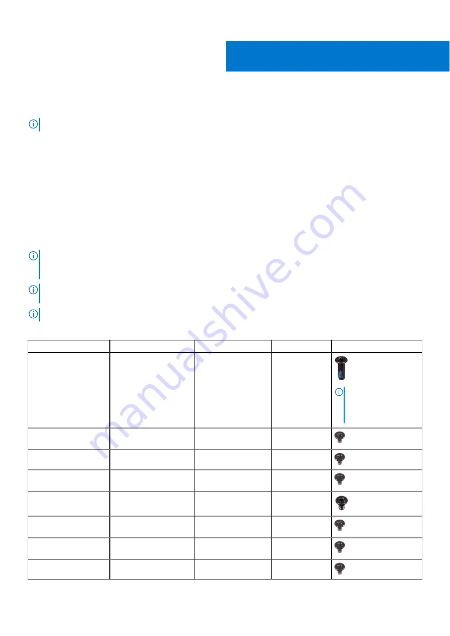
Screw image
Base cover
Palm-rest and keyboard
assembly
M2 x 7
6
NOTE:
Screw color
may vary depending
on the configuration
ordered.
Battery
Palm-rest and keyboard
assembly
M2 x 3
2
Solid-state drive
Solid-state drive bracket
M2 x 3
1
Hard-drive assembly
Palm-rest and keyboard
assembly
M2 x 3
3
Hard-drive bracket
Hard-drive assembly
M3 x 3
4
Left fan
Palm-rest and keyboard
assembly
M2 x 3
2
Right fan
Palm-rest and keyboard
assembly
M2 x 3
2
Wireless-card bracket
System board
M2 x 3
1
2
Removing and installing components
9
Содержание G3 15 3500
Страница 1: ...Dell G3 15 3500 Service Manual Regulatory Model P89F Regulatory Type P89F002 August 2021 Rev A02 ...
Страница 15: ...Steps 1 Connect the battery cable to the system board if applicable Removing and installing components 15 ...
Страница 26: ...26 Removing and installing components ...
Страница 49: ...Removing and installing components 49 ...


