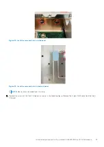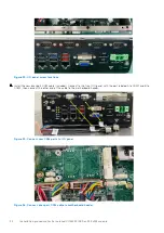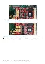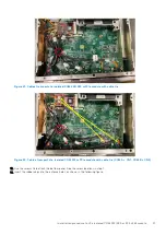
Figure 32. Install screws and nuts on side panel
Figure 33. Install screws and nuts on bottom panel
NOTE:
Reuse screws removed from this step.
7. Remove the screws of the front I/O panel, as shown in the following figure. Remove the 4-port COM cable from the front
I/O panel.
Installation procedure for 2x isolated COM 422/485 or 232 uFM module
23
Содержание EMC Edge Gateway 5200
Страница 1: ...Dell EMC Edge Gateway 5200 Service Manual January 2022 Rev A00 ...
Страница 19: ...Figure 26 Reattach the bottom panel Installation procedure for 4G and 5G expansion modules 19 ...
Страница 28: ...Figure 43 Antenna hole caps 28 Installation procedure for 2x isolated COM 422 485 or 232 uFM module ...
Страница 46: ...Figure 80 Antenna hole caps 46 Installation procedure for 2x GbE LAN uFM module ...


