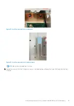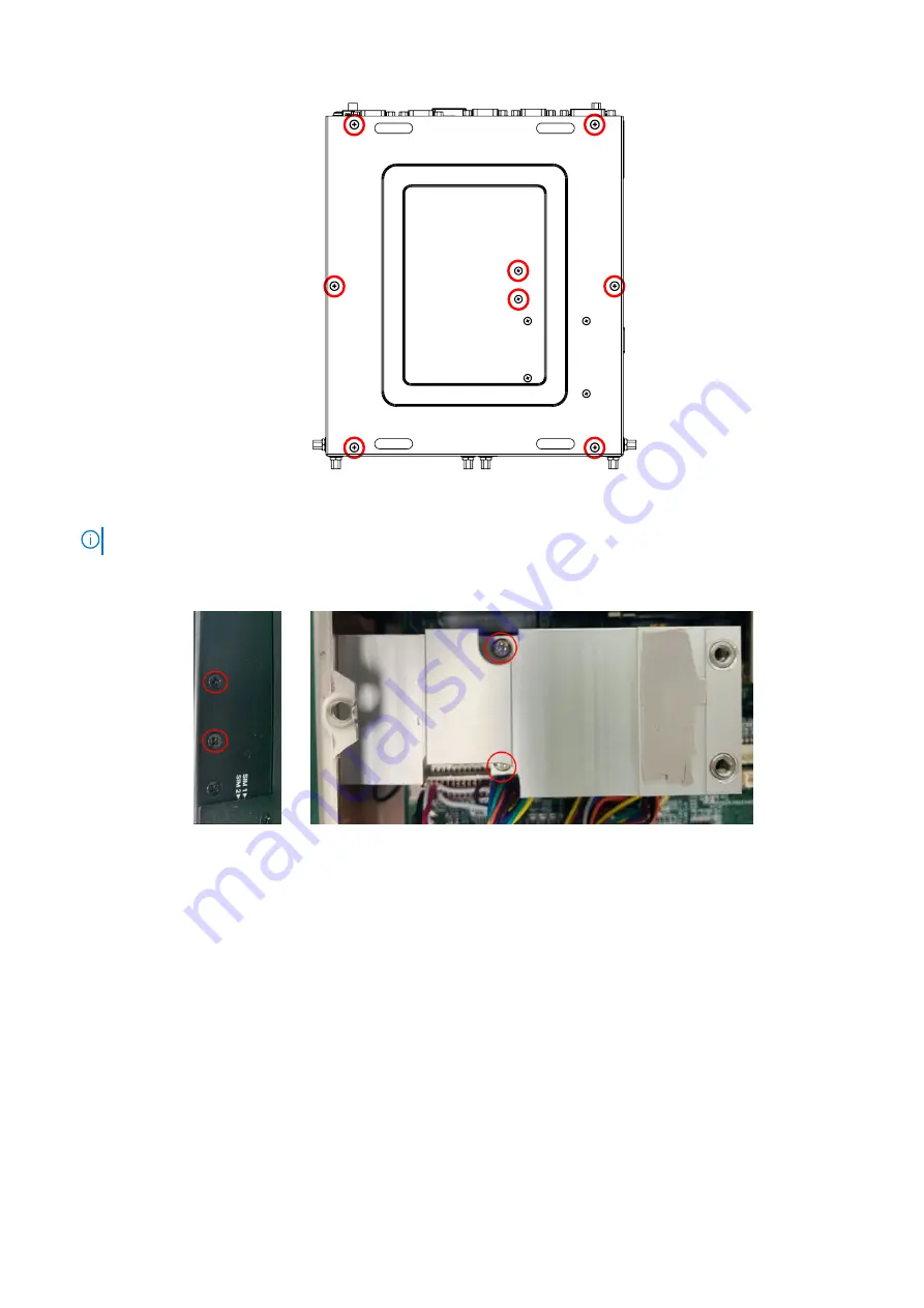
Figure 27. Bottom panel screw locations
NOTE:
If 4G or 5G is installed, you must also remove the remaining four screws.
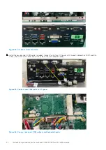
2. To access the mPCIe assembly beneath, remove the heat sink. Remove the screws of the heat sink to the side panel and
motherboard, as shown in the following figures.
Figure 28. Heat sink screw locations
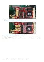
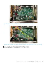
3. Remove the screws that secure the mPCIe assembly to the motherboard, and disconnect the WiFi cables, as shown in the
following figure, then remove the assembly (M.2 to mPCIe adapter board and WiFi card) from the motherboard.
Installation procedure for 2x isolated COM 422/485 or 232 uFM module
21
Содержание EMC Edge Gateway 5200
Страница 1: ...Dell EMC Edge Gateway 5200 Service Manual January 2022 Rev A00 ...
Страница 19: ...Figure 26 Reattach the bottom panel Installation procedure for 4G and 5G expansion modules 19 ...
Страница 28: ...Figure 43 Antenna hole caps 28 Installation procedure for 2x isolated COM 422 485 or 232 uFM module ...
Страница 46: ...Figure 80 Antenna hole caps 46 Installation procedure for 2x GbE LAN uFM module ...


