background image

A d d i n g   Pa r t s

63

5

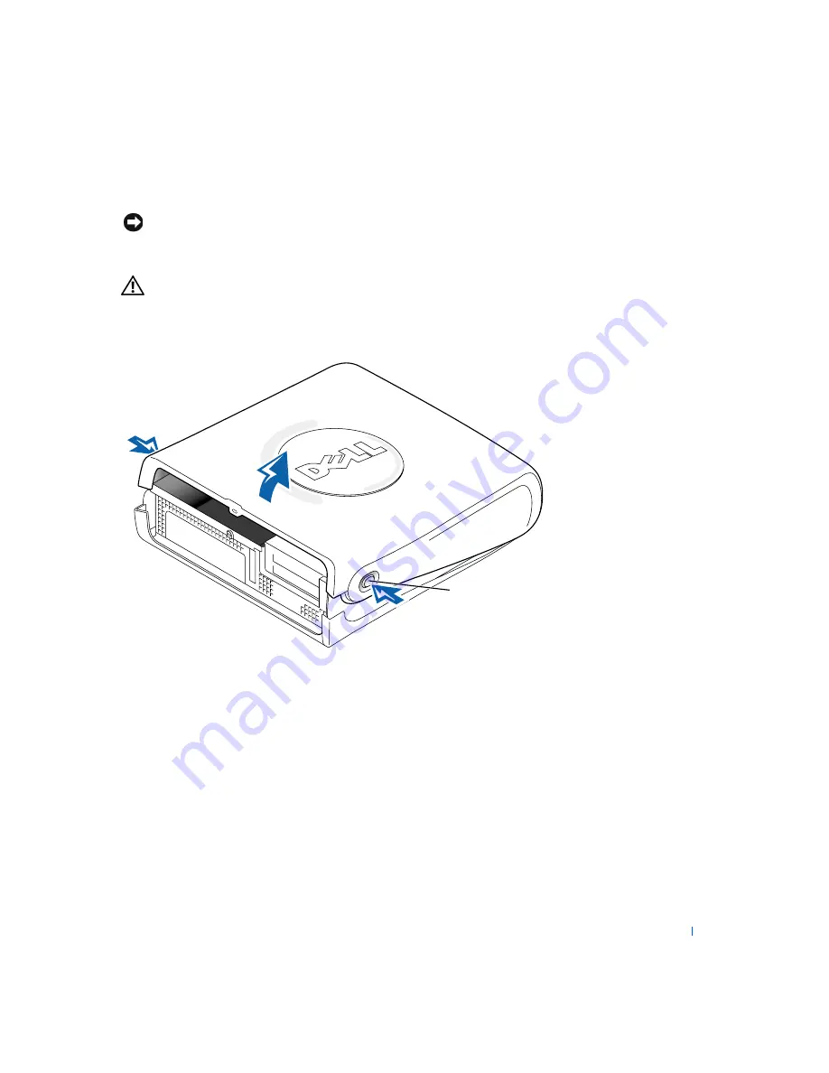
Press the two release buttons until the cover is free to swing up.


NOTICE: 

Open the cover slowly to ensure that you do not damage any cables.

6

Raise the back of the cover, and pivot it toward the front of the 
computer.


CAUTION: 

If the system board standby power light is on (see 

page 65), the computer is still plugged into an electrical outlet. 
Unplug the computer from the electrical outlet before 
proceeding.

release buttons 
(one on each side)

back of computer

Содержание Dimension 4500S

Страница 1: ...w w w d e l l c o m s u p p o r t d e l l c o m Dell Dimension 4500S ...

Страница 2: ...s and DellNet are trademarks of Dell Computer Corporation EMC is the registered trademark of EMC Corporation Intel Celeron and Pentium are registered trademarks of Intel Corporation Microsoft and Windows are registered trademarks of Microsoft Corporation Othertrademarksandtradenamesmaybeusedinthisdocumenttorefertoeithertheentitiesclaiming themarksandnamesortheirproducts DellComputerCorporationdisc...

Страница 3: ...etting Up Attaching and Removing the Computer Stand 16 Connecting a Printer 18 Parallel Printer 18 USB Printer 19 Installing the Printer Driver 19 Transferring Information to a New Computer 20 Setting Up a Home and Office Network 21 Connecting to a Network Adapter 21 Network Setup Wizard 21 Turning Off the Computer 22 2 Solving Problems Finding Solutions 24 Finding Help Information 26 Battery Prob...

Страница 4: ...ogram crashes repeatedly 33 A program is designed for an earlier Windows operating system 33 A solid blue screen appears 34 Other software problems 34 Other technical problems 35 General hardware problems 35 Keyboard Problems 36 Mouse Problems 37 Network Problems 38 Power Problems 39 Printer Problems 41 Scanner Problems 42 Sound and Speaker Problems 43 No sound from speakers 43 No sound from headp...

Страница 5: ... Windows XP Device Driver Rollback 53 Using the Dell Dimension ResourceCD 53 Resolving Software and Hardware Incompatibilities 54 Reinstalling Windows XP 55 4 Adding Parts Front and Back View of the Computer 60 Front View 60 Back View 61 Opening the Computer Cover 62 Looking Inside Your Computer 64 System Board 65 Adding Cards 66 Adding Memory 70 Removing a Memory Module 71 Adding a Memory Module ...

Страница 6: ...Items for Warranty Repair or Credit 99 Regulatory Information 99 FCC Notices U S Only 101 NOM Information Mexico Only 103 Limited Warranties and Return Policy 104 One Year Limited Warranty U S Only 104 Two Year Limited Warranty U S Only 106 Three Year Limited Warranty U S Only 110 Four Year Limited Warranty U S Only 113 One Year Limited Warranty Canada Only 116 Two Year Limited Warranty Canada Onl...

Страница 7: ...e of the computer for its operating voltage An auto sensing voltage circuit Computers with an auto sensing voltage circuit do not have a voltage selection switch on the back panel and automatically detect the correct operating voltage A manual voltage selection switch Computers with a voltage selection switch on the back panel must be manually set to operate at the correct operating voltage To hel...

Страница 8: ...er when disconnecting a network cable first unplug the cable from the network adapter on the back of your computer and then from the network jack When reconnecting a network cable to your computer first plug the cable into the network jack and then into the network adapter To help avoid possible damage to the system board wait 5 seconds after turning off the computer before disconnecting or connec...

Страница 9: ...ore you open the computer cover perform the following steps in the sequence indicated CAUTION Do not attempt to service the computer yourself except as explained in this guide and elsewhere in Dell documentation Always follow installation and service instructions closely 1 Perform an orderly computer shutdown using the operating system menu see page 22 2 Turn off your computer and any devices 3 Gr...

Страница 10: ...ent static damage discharge static electricity from your body before you touch anything inside your computer and periodically while you work inside the computer You can do so by touching an unpainted metal surface on the back of the computer You can also take the following steps to prevent static damage Do not remove items from their antistatic packing material until you are ready to install them ...

Страница 11: ... can use this CD to access documentation and reinstall drivers see page 53 How to set up a printer How to troubleshoot and solve problems How to add parts How to contact Dell Warranty information O w n e r s M a n u a l Express Service Code and Service Tag Number Windows License Label E x p r e s s S e r vi c e C o d e a n d W i n d o w s L i c e n s e L ab e l Located on your computer ...

Страница 12: ...rs and technical support Documentation for my computer D e l l S u p p o r t w e b s i t e The Dell Support website provides several online tools including Knowledge Base hints tips and online courses Customer Forum online discussion with other Dell customers Upgrades upgrade information for components such as memory the hard drive and the operating system Customer Care contact information order s...

Страница 13: ...ick User and system guides and then click User s guides 3 Click Tell Me How How to use Windows XP Documentation for my computer and devices W i n d o w s X P H e l p a n d S u p p o r t C e n t e r 1 Click the Start button and then click Help and Support 2 Type a word or phrase that describes your problem and then click the arrow icon 3 Click the topic that describes your problem 4 Follow the inst...

Страница 14: ...14 Safety Instructions w w w d e l l c o m s u p p o r t d e l l c o m ...

Страница 15: ...S E C T I O N 1 Attaching and Removing the Computer Stand Connecting a Printer Transferring Information to a New Computer Setting Up a Home and Office Network Turning Off the Computer ...

Страница 16: ... position you must attach the computer stand 1 Place the computer on its right side so that the drive bays are at the bottom 2 Fit the stand onto what was the left side of the computer a Position the stand as shown in the following illustration by aligning the large round hole in the stand with the securing button on the side of the cover and aligning the captive screw in the stand with the screw ...

Страница 17: ... so that the stand is at the bottom and the drives are at the top To remove the stand 1 Turn the computer over so that the stand is at the top 2 Loosen the thumbscrew and lift the stand away 3 Place the computer in a horizontal position ...

Страница 18: ...llowing sections Parallel Printer 1 Turn off the computer see page 22 NOTICE Use only a standard IEEE parallel cable measuring 3 m 10 ft or less to connect the printer to the computer Use of a nonstandard cable may prevent the printer from working 2 Attach the parallel printer cable to the parallel connector on the computer and tighten the two screws Attach the cable to the parallel connector on t...

Страница 19: ...nnectors inside the door on the front panel see page 60 Installing the Printer Driver If you need to install a printer driver insert the printer installation CD into the CD or DVD drive Then follow the prompts on the screen using the instructions that came with the printer If your printer installation CD does not automatically run click the Start button on the Microsoft Windows desktop click Run a...

Страница 20: ...other First you collect the data from the source computer and then you import the data to the new computer If the source computer uses another Windows operating system the wizard can be launched from the Windows XP operating system CD or from a floppy disk created on the Windows XP computer You can transfer the data to the new computer over a network or serial connection or you can store it on a r...

Страница 21: ...uters in a home or small office 1 Click the Start button point to All Programs Accessories Communications and then click Network Setup Wizard 2 On the welcome screen click Next 3 Click checklist for creating a network HINT Selecting the connection method This computer connects directly to the Internet enables the integrated firewall provided with Windows XP 4 Complete the checklist and required pr...

Страница 22: ...ower button HINT If you are having difficulty turning off your computer see General Problems on page 33 1 Save and close any open files and exit any open programs 2 Click the Start button and then click Turn off Computer 3 Click Turn off The computer automatically turns off after the shutdown process finishes 4 Turn off your monitor and any other devices connected to power ...

Страница 23: ...tion Battery Problems Drive Problems E Mail Modem and Internet Problems Error Messages General Problems Keyboard Problems Mouse Problems Network Problems Power Problems Printer Problems Scanner Problems Sound and Speaker Problems Video and Monitor Problems ...

Страница 24: ...s difficult to figure out where to go for answers Use this chart to help you quickly find the answers to your questions See page 39 See page 31 Get technical assistance from Dell See page 84 Press a key or move the mouse See the Tell Me How help file for information on standby mode ...

Страница 25: ...Solving Problems 25 See page 44 See page 43 See page 41 See page 30 See page 37 See page 36 See page 27 See page 38 See page 33 See page 42 See page 31 See page 30 See page 30 See page 33 ...

Страница 26: ...click Help and Support 2 Click User and system guides and then click User s guides 3 Click Tell Me How TO ACCESS WINDOWS HELP 1 Click the Start button and then click Help and Support 2 Type a word or phrase that describes your problem and then click the arrow icon 3 Click the topic that describes your problem 4 Follow the instructions shown on the screen TO LOCATE ADDITIONAL INFORMATION FOR YOUR C...

Страница 27: ...n with your antivirus software to check for and remove viruses Viruses can sometimes prevent Windows from recognizing the drive TEST THE DRIVE Insert another disk to eliminate the possibility that the original floppy disk is defective Insert a bootable floppy disk and reboot the computer ENSURE THAT THE DISK IS NOT FULL OR WRITE PROTECTED Ensure that the disk has available space and that it is not...

Страница 28: ...t up Ensure that the sound is not muted by clicking any boxes that are checked TEST THE DRIVE WITH ANOTHER CD Insert another CD to eliminate the possibility that the original CD is defective CHECK THE SPEAKERS AND SUBWOOFER See Sound and Speaker Problems on page 43 ENSURE THAT WINDOWS RECOGNIZES THE DRIVE Double click My Computer on the desktop If the CD drive is not listed perform a full scan wit...

Страница 29: ...program to record CD RWs TEST THE DRIVE WITH ANOTHER DVD Insert another DVD to eliminate the possibility that the original DVD is defective ENSURE THAT WINDOWS RECOGNIZES THE DRIVE Double click My Computer on the desktop If the DVD drive is not listed perform a full scan with your antivirus software to check for and remove viruses Viruses can sometimes prevent Windows from recognizing the drive CL...

Страница 30: ...wering machine fax machine surge protector or line splitter then bypass them and use the telephone to connect the modem directly to the telephone wall jack USE A DIFFERENT TELEPHONE LINE If you are using a line that is 3 m 10 ft or more in length try a shorter one RUN THE MODEM HELPER DIAGNOSTICS Click the Start button point to Programs and then click Modem Helper Follow the instructions on the sc...

Страница 31: ...ark in it 6 Select the disable code from the drop down menu for example 70 7 Click Apply and then click OK ENSURE THAT YOU ARE CONNECTED TO THE INTERNET With the Outlook Express e mail program open click File If Work Offline has a checkmark next to it click the checkmark to remove it and connect to the Internet ENSURE THAT YOU HAVE SUBSCRIBED TO AN INTERNET SERVICE PROVIDER Contact an Internet ser...

Страница 32: ...y disk or CD NON SYSTEM DISK ERROR A floppy disk is in the floppy drive Remove the floppy disk and restart the computer NOT ENOUGH MEMORY OR RESOURCES CLOSE SOME PROGRAMS AND TRY AGAIN You have too many programs open Close all windows and open the program that you want to use In some cases you might have to restart your computer to restore computer resources If so try running the program that you ...

Страница 33: ... perform an operating system shutdown END THE PROGRAM 1 Press Ctrl Shift Esc simultaneously 2 Click Applications 3 Click the program that is no longer responding 4 Click End Task CHECK THE SOFTWARE DOCUMENTATION Many software manufacturers maintain websites with information that may help you solve the problem Ensure that you properly installed and configured the program If necessary uninstall and ...

Страница 34: ... YOU HAVE NOT MADE AN ERROR WHILE ENTERING DATA See the program documentation to make sure that the values or characters you are entering are valid CHECK FOR VIRUSES Use a virus scanning program to check the hard drive floppy disks or CDs RESTART THE COMPUTER Save and close any open files exit any open programs and then shut down your computer through the Start menu instead of pressing the power b...

Страница 35: ... SUPPORT WEBSITE Go to support dell com for help with general usage installation and troubleshooting questions See Dell Technical Support Policy on page 83 for a description of the hardware and software support provided by Dell E MAIL DELL Go to the Dell Support website and then click E Mail Dell in the Communicate list Send an e mail message to Dell about your problem you can expect to receive an...

Страница 36: ...tart the computer If the computer does not respond to a keystroke or the mouse press the power button for at least 8 to 10 seconds until the computer turns off Press the power button again to restart the computer CHECK THE KEYBOARD CABLE Shut down the computer see page 22 reconnect the keyboard cable as shown on the Start Here setup diagram for your computer and then restart the computer Ensure th...

Страница 37: ... IF YOU CONNECTED THE MOUSE AFTER TURNING ON THE COMPUTER REMOVE THE POWER CABLE AND THEN RECONNECT THE MOUSE CABLE If the mouse is connected after the power is turned on the mouse appears to be nonfunctional To make the mouse function properly 1 While your computer is on remove the power cable from the back of the computer 2 Connect the mouse to the computer 3 Reconnect the power cable 4 Turn on ...

Страница 38: ...PT REQUEST CONFLICTS See page 54 CHECK THE NETWORK CABLE CONNECTOR Ensure that the network cable is connected as shown on page 21 CHECK THE NETWORK LIGHTS ON THE BACK OF THE COMPUTER No light indicates that there is no network communication Try replacing the network cable These lights indicate there is network communcation Green light indicates a 10 Mbps network connection Orange light indicates a...

Страница 39: ... or the person who set up your network to verify that your network settings are correct and that the network is functioning CHECK FOR INTERRUPT REQUEST CONFLICTS See page 54 ADJUST THE POWER PROPERTIES Your computer may be in standby or hibernate mode For information on power conservation modes see the Tell Me How help file or search for the keyword standby or hibernate in Windows Help To access h...

Страница 40: ...ocessor power cable is securely connected to the system board see page 65 Ensure that the power supply cables are securely connected to the system board see page 65 If the problem persists contact Dell see page 84 IF THE POWER LIGHT IS STEADY AMBER The computer is receiving electrical power but an internal power problem might exist Ensure that the power cable is firmly inserted into both the power...

Страница 41: ...on for power button information VERIFY THE PRINTER CABLE CONNECTIONS See the printer documentation for cable connection information Ensure that the printer cables are securely connected to the printer and the computer see page 18 TEST THE ELECTRICAL OUTLET Ensure that the electrical outlet is working by testing it with another device such as a lamp VERIFY THAT THE PRINTER IS RECOGNIZED BY WINDOWS ...

Страница 42: ...ocking tab or button RESTART THE COMPUTER AND TRY THE SCANNER AGAIN CHECK THE CABLE CONNECTIONS If your scanner has a power cable ensure that the power cable is firmly connected to a working electrical outlet and that the scanner is turned on Ensure that the scanner cable is firmly connected to the computer and to the scanner VERIFY THAT THE SCANNER IS RECOGNIZED BY MICROSOFT WINDOWS 1 Click the S...

Страница 43: ... Click or double click the speaker icon in the lower right corner of your screen Ensure that the volume is turned up and that the sound is not muted DISCONNECT HEADPHONES FROM THE HEADPHONE CONNECTOR Sound from the speakers is automatically disabled when headphones are connected to the computer s front panel headphone connector TEST THE ELECTRICAL OUTLET Ensure that the electrical outlet is workin...

Страница 44: ...o for this CD ROM device box ADJUST THE WINDOWS VOLUME CONTROL Click or double click the speaker icon in the lower right corner of your screen Ensure that the volume is turned up and that the sound is not muted CHECK THE MONITOR POWER LIGHT If the power light is off firmly press the button to ensure that the monitor is turned on If the power light is lit or blinking the monitor has power If the po...

Страница 45: ...aussing the monitor and running the monitor self test MOVE THE SUBWOOFER AWAY FROM THE MONITOR If your speaker system includes a subwoofer ensure that the subwoofer is at least 60 cm 2 ft away from the monitor MOVE THE MONITOR AWAY FROM EXTERNAL POWER SOURCES Fans fluorescent lights halogen lamps and other electrical devices can cause the screen image to appear shaky Turn off nearby devices to che...

Страница 46: ...s w w w d e l l c o m s u p p o r t d e l l c o m RESTORE THE RECOMMENDED SETTINGS Restore the original resolution and refresh rate settings See the Tell Me How help file for instructions To access help files see page 26 ...

Страница 47: ...S E C T I O N 3 Diagnostic Lights Using System Restore Reinstalling Drivers Resolving Software and Hardware Incompatibilities Reinstalling Windows XP ...

Страница 48: ...ory module installed reinstall it see page 70 and then restart the computer If you have two or more memory modules installed remove the modules reinstall one module see page 70 and then restart the computer If the computer starts normally reinstall an additional module Continue until you identify a faulty module or reinstall all modules without error If available install properly working memory of...

Страница 49: ... 1 Determine if a conflict exists by removing a card see page 66 and then restarting the computer 2 If the problem persists reinstall the card that you removed remove a different card see page 66 and then restart the computer 3 Repeat this process for each card If the computer starts normally troubleshoot the last card removed from the computer for resource conflicts see Resolving Software and Har...

Страница 50: ...tore also includes the following features NOTICE Make regular backups of your data files System Restore does not monitor your data files or recover them Creating a Restore Point Using the System Restore Wizard 1 Click the Start button 2 Click Help and Support 3 Click System Restore 4 Follow the instructions on the screen Other failure Ensure that the cables are properly connected from the hard dri...

Страница 51: ... Driver Rollback see page 53 If that is unsuccessful then use System Restore NOTICE Before restoring the computer to an earlier operating state save and close all open files and close all open programs Do not alter open or delete any files or programs until the system restoration is complete 1 Click the Start button point to All Programs Accessories System Tools and then click System Restore 2 Ens...

Страница 52: ...E Before undoing the last system restore save and close all open files and close all open programs Do not alter open or delete any files or programs until the system restoration is complete 1 Click the Start button point to All Programs Accessories System Tools and then click System Restore 2 Select Undo my last restoration and click Next 3 Click Next The System Restore screen appears and then the...

Страница 53: ... System Restore see page 50 to return your operating system to the operating state it was in before you installed the new device driver To use Device Driver Rollback 1 Click the Start button and then right click My Computer 2 Click Properties 3 Click the Hardware tab and then click Device Manager 4 In the Device Manager window right click the device for which the new driver was installed and then ...

Страница 54: ...ceCD has identified these components in your system window 6 Click the driver that you want to reinstall and follow the instructions on the screen If a particular driver is not listed then that driver is not required by your operating system Microsoft Windows XP IRQ conflicts occur if a device either is not detected during the operating system setup or is detected but incorrectly configured To che...

Страница 55: ...resolve a hardware conflict on my computer 6 Click Next Before reinstalling the Microsoft Windows XP operating system to correct a problem try correcting the problem by performing a Windows XP System Restore see page 50 The reinstallation process can take 1 to 2 hours and you will need to reinstall your drivers virus protection program and other software when the process is complete NOTICE The Ope...

Страница 56: ...s F8 on your keyboard to agree with the license information 7 If your computer already has Windows XP installed and you want to recover your current Windows XP data type r to select the repair option and then go to step 16 If you want to install a new copy of Windows XP press Esc to select the fresh copy option and then press Enter on the next screen to select the highlighted partition recommended...

Страница 57: ... and Time Settings window and then click Next 14 If you have a network card in your computer select the appropriate network settings If you do not have a network card this option does not appear Windows XP begins to install its components and configure the computer The computer automatically restarts 15 When the Welcome to Microsoft screen appears click the green arrow icon at the bottom of the sc...

Страница 58: ...58 Advanced Troubleshooting w w w d e l l c o m s u p p o r t d e l l c o m ...

Страница 59: ...S E C T I O N 4 Front and Back View of the Computer Opening the Computer Cover Looking Inside Your Computer Adding Cards Adding Memory Closing the Computer Cover ...

Страница 60: ...o m Front View HINT The front panel door is removable if you remove it or accidentally knock it off its hinges it snaps back in place front door power button power light hard drive light floppy drive light USB connectors 2 headphone connector breakaway hinges 2 ...

Страница 61: ... USB connector 3 card slots The slots for PCI cards 4 power connector The connection for the power cable 5 voltage selection switch may not be available on all computers Your computer is equipped with either a fixed voltage power supply an auto sensing voltage circuit or a manual voltage selection switch See Safety Instructions on page 7 for more information 6 line in connector Use the blue line i...

Страница 62: ...out connector available on computers with integrated sound to attach headphones and most speakers with integrated amplifiers On computers with a sound card the line out connector is on the card 8 microphone connector Use the pink microphone connector available on computers with integrated sound to attach a personal computer microphone for voice or musical input into a sound or telephony program On...

Страница 63: ... not damage any cables 6 Raise the back of the cover and pivot it toward the front of the computer CAUTION If the system board standby power light is on see page 65 the computer is still plugged into an electrical outlet Unplug the computer from the electrical outlet before proceeding release buttons one on each side back of computer ...

Страница 64: ...from the electrical outlet before opening the cover NOTICE Be careful when opening the computer cover to ensure that you do not inadvertently disconnect cables from the system board hard drive card cage power supply heat sink and blower assembly system board floppy drive CD or DVD drive Your computer s hard drive may or may not have a plastic shroud cover Operating the computer without a hard driv...

Страница 65: ...processor connector CPU microprocessor fan connector FAN front panel switch connector FRONTPANEL On computers with integrated audio CD audio connector CD IN front panel audio cable connector FRONTAUDIO telephony voice modem connector MODEM configuration jumper PSWD page 80 back of computer card cage connector PCI2 page 66 power connector 12VPOWER unused connector standby power light AUX_PWR clear ...

Страница 66: ...mputer see page 22 2 Turn off any attached devices and disconnect them from their electrical outlets NOTICE To disconnect a network cable first unplug the cable from your computer and then unplug it from the network wall jack 3 Disconnect the computer power cable from the wall outlet and then press the power button to ground the system board 4 Remove the computer stand if it is attached see page 1...

Страница 67: ...Adding Parts 67 b Gently pull on the handle and lift the card cage up and away from the computer card cage ...

Страница 68: ...is already installed in the computer remove the card If necessary disconnect any cables connected to the card Grasp the card by its top corners and ease it out of its connector 9 Prepare the card for installation See the documentation that came with the card for information on configuring the card making internal connections or otherwise customizing it for your computer edge connector card card ca...

Страница 69: ...d of the card into the card guide bracket as you lower the card toward its connector on the system board Insert the card firmly into the card connector on the riser board 11 Lower the retention arm and press it into place securing the card s in the computer 12 Replace the card cage a Align the tabs in the side of the card cage with the slots on the side of the computer and slide the card cage down...

Страница 70: ...ard documentation CAUTION Before you begin any of the procedures in this section follow the safety instructions on page 7 CAUTION To guard against electrical shock always unplug your computer from the electrical outlet before opening the cover You can increase your computer memory by installing memory modules on the system board For information on the type of memory supported by your computer look...

Страница 71: ...e connector Adding a Memory Module 1 Press out the securing clip at each end of the memory module connector 2 Align the notch on the bottom of the module with the crossbar in the connector NOTICE To avoid damage to the memory module press the module straight down into the socket with equal force applied at each end of the module securing clips 2 notch step 1 memory module cutouts 2 connector step ...

Страница 72: ...uter and devices to electrical outlets and turn them on 7 Right click the My Computer icon and then click Properties 8 Click the General tab 9 To verify that the memory is installed correctly check the amount of memory RAM listed 1 Ensure that all cables are connected and fold cables out of the way Make sure cables are not routed over the drive cage they will prevent the cover from closing properl...

Страница 73: ...T I O N 5 Specifications Standard Settings Clearing Forgotten Passwords Replacing the Battery Dell Technical Support Policy U S Only Contacting Dell Regulatory Information Limited Warranties and Return Policy ...

Страница 74: ... System Information System chip set Intel 845 G DMA channels seven Interrupt levels 24 APIC mode System BIOS chip 4 Mb 512 KB System clock 400 or 533 MHz data rate Expansion Bus Bus types PCI Bus speed PCI 33 MHz PCI connectors two PCI connector size 120 pins PCI connector data width maximum 32 bits Memory Architecture DDR SDRAM Memory connectors two Memory capacities 128 256 384 512 or 768 MB or ...

Страница 75: ...tional Video 15 hole connector Keyboard 6 pin mini DIN connector or USB connector Mouse 6 pin mini DIN connector or USB connector USB two front panel and four back panel USB 2 0 compliant connectors Headphone front panel miniature jack Audio three miniature jacks for line in line out and microphone Internally accessible Primary IDE channel 40 pin connector on PCI local bus Secondary IDE channel 40...

Страница 76: ...W Heat dissipation 500 BTU fully loaded computer without monitor Voltage see page 7 for important voltage setting information fixed voltage power supply 110 V at 50 60 Hz manual selection and auto sensing power supplies 90 to 135 V at 50 60 Hz 180 to 265 V at 50 60 Hz 100 V at 50 60 Hz for Japanese computers Backup battery 3 V CR2032 coin cell Physical Height x Width x Depth 10 6 x 38 9 x 43 2 cm ...

Страница 77: ...e min Maximum shock Operating bottom half sine pulse with a change in velocity of 50 8 cm sec 20 inches sec Storage 23 G faired square wave with a velocity change of 508 cm sec 200 inches sec Altitude Operating 15 2 to 3048 m 50 to 10 000 ft 2 Storage 15 2 to 10 670 m 50 to 35 000 ft 2 At 35 C 95 F the maximum operating altitude is 914 m 3000 ft ...

Страница 78: ...tup program contains the standard settings for your computer NOTICE Unless you are an expert computer user don t change the settings for this program Certain changes might make your computer work incorrectly See the following figure for an example of the main program screen ...

Страница 79: ...e title that display the system processor L2 cache service tag and the version number of the BIOS Options A scrollable box listing options that define the configuration of your computer including installed hardware power conservation and security features Fields to the right of the listed options contain settings or values The settings and values that you can change are brighter on the screen All ...

Страница 80: ...outlet and then press the power button to ground the system board 4 Remove the computer stand if it is attached see page 17 5 Open the computer cover see page 62 6 Locate jumper PSWD on the system board see page 65 and remove the jumper plug 7 Close the computer cover see page 72 plug your computer into an electrical outlet and turn on the computer The existing password s will be erased 8 Shut dow...

Страница 81: ...l years If you have to repeatedly reset time and date information after turning on the computer replace the battery CAUTION A new battery can explode if it is incorrectly installed Replace the 3 V CR2032 battery only with the same or equivalent type recommended by the manufacturer Discard used batteries according to the manufacturer s instructions 1 Record all the screens in the system setup progr...

Страница 82: ...t with the side labeled facing up and snap it into place 7 Attach the computer stand optional see page 16 8 Connect your computer and devices to electrical outlets and turn them on NOTICE To connect a network cable first plug the cable into the network wall jack and then plug it into the computer 9 Access the system setup program see page 78 and restore the settings you recorded in step 1 10 Prope...

Страница 83: ... Integration DellPlus 2 1 Repair services are provided pursuant to the terms and conditions of your limited warranty and any optional support service contract purchased with the computer 2 All Dell standard components included in a Custom Factory Integration CFI project are covered by the standard Dell limited warranty for your computer However Dell also extends a parts replacement program to cove...

Страница 84: ...ge 83 for a description of the hardware and software support provided by Dell Contact Numbers and Addresses Country City International Access Code Country Code City Code Department Name or Service Area Website and E Mail Address Area Codes Local Numbers and Toll Free Numbers Antigua and Barbuda General Support 1 800 805 5924 Argentina Buenos Aires International Access Code 00 Country Code 54 City ...

Страница 85: ...Home Small Business Sales toll free 0800 16884 Corporate Sales 02 481 91 00 Fax 02 481 92 99 Switchboard 02 481 91 00 Website support euro dell com E mail tech_be dell com E mail for French Speaking Customers support euro dell com be fr emaildell Bermuda General Support 1 800 342 0671 Brazil International Access Code 00 Country Code 55 City Code 51 Customer Support Technical Support 0800 90 3355 T...

Страница 86: ...de 2 Sales Customer Support and Technical Support toll free 1230 020 4823 China Xiamen Country Code 86 City Code 592 Home and Small Business Technical Support toll free 800 858 2437 Corporate Accounts Technical Support toll free 800 858 2333 Customer Experience toll free 800 858 2060 Home and Small Business toll free 800 858 2222 Preferred Accounts Division toll free 800 858 2062 Large Corporate A...

Страница 87: ...er Care 3287 5505 Switchboard Relational 3287 1200 Fax Switchboard Relational 3287 1201 Switchboard Home Small Business 3287 5000 Fax Switchboard Home Small Business 3287 5001 Website support euro dell com E mail Support Portable Computers den_nbk_support dell com E mail Support Desktop Computers den_support dell com E mail Support Servers Nordic_server_support dell com Dominican Republic General ...

Страница 88: ...ity Codes 1 4 Home and Small Business Technical Support 0825 387 270 Customer Care 0825 823 833 Switchboard 0825 004 700 Switchboard Calls from outside of France 04 99 75 40 00 Sales 0825 004 700 Fax 0825 004 701 Fax Calls from outside of France 04 99 75 40 01 Website support euro dell com E mail support euro dell com fr fr emaildell Corporate Technical Support 0825 004 719 Customer Care 0825 338 ...

Страница 89: ...on Sales toll free 800 96 4109 Corporate Sales toll free 800 96 4108 India Technical Support 1600 33 8045 Sales 1600 33 8044 Ireland Cherrywood International Access Code 16 Country Code 353 City Code 1 Ireland Technical Support 1850 543 543 UK Technical Support dial number within UK only 0870 908 0800 Home User Customer Care 01 204 4095 Small Business Customer Care 01 204 4444 UK Customer Care dia...

Страница 90: ...bsite support euro dell com E mail support euro dell com it it zdell Corporate Technical Support 02 577 826 90 Customer Care 02 577 825 55 Fax 02 575 035 30 Switchboard 02 577 821 Website support euro dell com E mail support euro dell com it it emaildell Jamaica General Support 1 800 682 3639 Country City International Access Code Country Code City Code Department Name or Service Area Website and ...

Страница 91: ... 3494 Preferred Accounts Division Sales Over 400 employees 044 556 3433 Large Corporate Accounts Sales Over 3500 employees 044 556 3440 Public Sales Government agencies educational institutions and medical institutions 044 556 3440 Global Segment Japan 044 556 3469 Individual User 044 556 1657 Faxbox Service 044 556 3490 Switchboard 044 556 4300 Website support jp dell com Korea Seoul Internationa...

Страница 92: ...russels Belgium 02 481 91 00 Customer Care Brussels Belgium 02 481 91 19 Fax Brussels Belgium 02 481 92 99 Switchboard Brussels Belgium 02 481 91 00 Website support euro dell com E mail tech_be dell com Macau Country Code 853 Technical Support toll free 0800 582 Customer Service Penang Malaysia 604 633 4949 Transaction Sales toll free 0800 581 Malaysia Penang International Access Code 00 Country C...

Страница 93: ...0 581 8740 Home Small Business Sales toll free 0800 0663 Home Small Business Sales Fax 020 682 7171 Corporate Sales 020 581 8818 Corporate Sales Fax 020 686 8003 Fax 020 686 8003 Switchboard 020 581 8818 Website support euro dell com E mail tech_nl dell com New Zealand International Access Code 00 Country Code 64 Home and Small Business 0800 446 255 Government and Business 0800 444 617 Sales 0800 ...

Страница 94: ...oland Warsaw International Access Code 011 Country Code 48 City Code 22 Customer Service Phone 57 95 700 Customer Care 57 95 999 Sales 57 95 999 Customer Service Fax 57 95 806 Reception Desk Fax 57 95 998 Switchboard 57 95 999 Website support euro dell com E mail pl_support dell com Portugal International Access Code 00 Country Code 35 Technical Support 800 834 077 Customer Care 800 300 415 or 800...

Страница 95: ...Southeast Asian and Pacific Countries Customer Technical Support Customer Service and Sales Penang Malaysia 604 633 4810 Spain Madrid International Access Code 00 Country Code 34 City Code 91 Home and Small Business Technical Support 902 100 130 Customer Care 902 118 540 Sales 902 118 541 Switchboard 902 118 541 Fax 902 118 539 Website support euro dell com E mail support euro dell com es es email...

Страница 96: ...rporate 0844 822 844 Customer Care Home and Small Business 0848 802 202 Customer Care Corporate 0848 821 721 Fax 022 799 01 90 Switchboard 022 799 01 01 Website support euro dell com E mail swisstech dell com E mail for French Speaking HSB and Corporate Customers support euro dell com ch fr emaildell Taiwan International Access Code 002 Country Code 886 Technical Support toll free 0080 60 1255 Tec...

Страница 97: ...r Care 0870 908 0500 Preferred Accounts 500 5000 employees Customer Care 01344 373 196 Central Government Customer Care 01344 373 193 Local Government Education Customer Care 01344 373 199 Health Customer Care 01344 373 194 Home and Small Business Sales 0870 907 4000 Corporate Public Sector Sales 01344 860 456 Website support euro dell com Customer Care Website dell co uk lca customerservices E ma...

Страница 98: ...rs toll free 1 800 822 8965 Public Americas Computers purchased by governmental agencies local state or federal medical institutions or educational institutions Customer Service and Technical Support Return Material Authorization Numbers toll free 1 800 234 1490 Dell Sales toll free 1 800 289 3355 or toll free 1 800 879 3355 Spare Parts Sales toll free 1 800 357 3355 Desktop and Portable Fee Based...

Страница 99: ... you assume the risk of loss during shipment to Dell Collect on delivery packages are not accepted Returns that are missing any of the preceding requirements will be refused at our receiving dock and returned to you Electromagnetic Interference EMI is any signal or emission radiated in free space or conducted along power or signal leads that endangers the functioning of a radio navigation or other...

Страница 100: ...ive or an experienced radio television technician for additional suggestions Dell computers are designed tested and classified for their intended electromagnetic environment These electromagnetic environment classifications generally refer to the following harmonized definitions Class A is typically for business or industrial environments Class B is typically for residential environments Informati...

Страница 101: ...uter examine all FCC registration labels located on the bottom or back panel of your computer on card mounting brackets and on the cards themselves If any one of the labels carries a Class A rating your entire computer is considered to be a Class A digital device If all labels carry an FCC Class B rating as distinguished by either an FCC ID number or the FCC logo your computer is considered to be ...

Страница 102: ...its for a Class B digital device pursuant to Part 15 of the FCC Rules These limits are designed to provide reasonable protection against harmful interference in a residential installation This equipment generates uses and can radiate radio frequency energy and if not installed and used in accordance with the manufacturer s instruction manual may cause interference with radio communications However...

Страница 103: ...cribed in this document in compliance with the requirements of the official Mexican standards NOM Exporter Dell Computer Corporation One Dell Way Round Rock TX 78682 Importer Dell Computer de México S A de C V Paseo de la Reforma 2620 11 Piso Col Lomas Altas 11950 México D F Ship to Dell Computer de México S A de C V al Cuidado de Kuehne Nagel de México S de R I Avenida Soles No 55 Col Peñon de lo...

Страница 104: ...hipping the products to you is covered under this limited warranty Otherwise this limited warranty does not cover damage due to external causes including accident abuse misuse problems with electrical power servicing not authorized by Dell usage not in accordance with product instructions failure to perform required preventive maintenance and problems caused by use of parts and components not supp...

Страница 105: ...ct s Remove any removable media such as floppy disks CDs or PC Cards Dell does not accept liability for lost data or software Dell owns all parts removed from repaired products Dell uses new and reconditioned parts made by various manufacturers in performing warranty repairs and building replacement products If Dell repairs or replaces a product its warranty term is not extended THIS LIMITED WARRA...

Страница 106: ...nce in which Dell issues a Return Material Authorization Number Dell must receive the product s for repair prior to the expiration of the warranty period in order for the repair s to be covered by the limited warranty Two Year Limited Warranty U S Only Dell Computer Corporation Dell manufactures its hardware products from parts and components that are new or equivalent to new in accordance with in...

Страница 107: ...to Dell s facility To request warranty service you must contact Dell s Customer Technical Support within the warranty period See Contacting Dell on page 84 to find the appropriate contact information for obtaining customer assistance If warranty service is required Dell will issue a Return Material Authorization Number You must ship the products back to Dell in their original or equivalent packagi...

Страница 108: ...le Shipments to other locations where applicable will be made freight collect Dell will include a prepaid shipping container with each replacement part for your use in returning the replaced part to Dell Replacement parts are new or reconditioned Dell may provide replacement parts made by various manufacturers when supplying parts to you The warranty term for a replacement part is the remainder of...

Страница 109: ...CCEPT LIABILITY BEYOND THE REMEDIES SET FORTH IN THIS LIMITED WARRANTY STATEMENT OR LIABILITY FOR INCIDENTAL OR CONSEQUENTIAL DAMAGES INCLUDING WITHOUT LIMITATION ANY LIABILITY FOR PRODUCTS NOT BEING AVAILABLE FOR USE OR FOR LOST DATA OR SOFTWARE SOME STATES OR JURISDICTIONS DO NOT ALLOW THE EXCLUSION OR LIMITATION OF INCIDENTAL OR CONSEQUENTIAL DAMAGES SO THE PRECEDING EXCLUSION OR LIMITATION MAY...

Страница 110: ...cordance with product instructions failure to perform required preventive maintenance and problems caused by use of parts and components not supplied by Dell This limited warranty does not cover any items that are in one or more of the following categories software external devices except as specifically noted accessories or parts added to a Dell system after the system is shipped from Dell access...

Страница 111: ...lost data or software Dell owns all parts removed from repaired products Dell uses new and reconditioned parts made by various manufacturers in performing warranty repairs and building replacement products If Dell repairs or replaces a product its warranty term is not extended Limited Warranty Coverage During Years Two and Three During the second and third years of this limited warranty Dell will ...

Страница 112: ...D TO REPAIR AND REPLACEMENT AS SET FORTH IN THIS LIMITED WARRANTY STATEMENT ALL EXPRESS AND IMPLIED WARRANTIES FOR THE PRODUCT INCLUDING BUT NOT LIMITED TO ANY IMPLIED WARRANTIES OF AND CONDITIONS OF MERCHANTABILITY AND FITNESS FOR A PARTICULAR PURPOSE ARE LIMITED IN DURATION TO THE WARRANTY PERIOD SET FORTH ABOVE AND NO WARRANTIES WHETHER EXPRESS OR IMPLIED WILL APPLY AFTER SUCH PERIOD SOME STATE...

Страница 113: ...xt Damage due to shipping the products to you is covered under this limited warranty Otherwise this limited warranty does not cover damage due to external causes including accident abuse misuse problems with electrical power servicing not authorized by Dell usage not in accordance with product instructions failure to perform required preventive maintenance and problems caused by use of parts and c...

Страница 114: ...ept liability for lost data or software Dell owns all parts removed from repaired products Dell uses new and reconditioned parts made by various manufacturers in performing limited warranty repairs and building replacement products If Dell repairs or replaces a product its limited warranty term is not extended Limited Warranty Coverage During Years Two Three and Four During the second third and fo...

Страница 115: ... AS SET FORTH IN THIS LIMITED WARRANTY STATEMENT ALL EXPRESS AND IMPLIED WARRANTIES FOR THE PRODUCT INCLUDING BUT NOT LIMITED TO ANY IMPLIED WARRANTIES OF AND CONDITIONS OF MERCHANTABILITY AND FITNESS FOR A PARTICULAR PURPOSE ARE LIMITED IN DURATION TO THE LIMITED WARRANTY PERIOD SET FORTH ABOVE AND NO WARRANTIES WHETHER EXPRESS OR IMPLIED WILL APPLY AFTER SUCH PERIOD SOME STATES OR JURISDICTIONS ...

Страница 116: ...e year beginning on the date of invoice as further described in the following text Damage due to shipping the products to you is covered under this limited warranty Otherwise this limited warranty does not cover damage due to external causes including accident abuse misuse problems with electrical power servicing not authorized by Dell usage not in accordance with product instructions failure to p...

Страница 117: ...the product s Remove any removable media such as floppy disks CDs or PC Cards Dell does not accept liability for lost data or software Dell owns all parts removed from repaired products Dell uses new and reconditioned parts made by various manufacturers in performing warranty repairs and building replacement products If Dell repairs or replaces a product its warranty term is not extended DELL MAKE...

Страница 118: ...ange In any instance in which Dell issues a Return Material Authorization Number Dell must receive the product s for repair prior to the expiration of the warranty period in order for the repair s to be covered by the limited warranty Two Year Limited Warranty Canada Only Dell Computer Corporation Dell manufactures its hardware products from parts and components that are new or equivalent to new i...

Страница 119: ...e returned to Dell s facility To request warranty service you must contact Dell s Customer Technical Support within the warranty period See Contacting Dell on page 84 to find the appropriate contact information for obtaining customer assistance If warranty service is required Dell will issue a Return Material Authorization Number You must ship the products back to Dell in their original or equival...

Страница 120: ...conditioned Dell may provide replacement parts made by various manufacturers when supplying parts to you The warranty term for a replacement part is the remainder of the limited warranty term You will pay Dell for replacement parts if the replaced part is not returned to Dell The process for returning replaced parts and your obligation to pay for replacement parts if you do not return the replaced...

Страница 121: ... to Dell s two year limited warranty only For provisions of any service contract covering your system refer to your invoice or the separate service contract that you will receive If Dell elects to exchange a system or component the exchange will be made in accordance with Dell s Exchange Policy in effect on the date of the exchange In any instance in which Dell issues a Return Material Authorizati...

Страница 122: ...program are not covered Batteries for portable computers are covered only during the initial one year period of this limited warranty Limited Warranty Coverage During Year One During the one year period beginning on the invoice date Dell will repair or replace products covered under this limited warranty that are returned to Dell s facility To request warranty service you must contact Dell s Custo...

Страница 123: ...ve Dell ship the replacement part Dell will ship parts freight prepaid if you use an address in Canada where applicable Shipments to other locations will be made freight collect Dell will include a prepaid shipping container with each replacement part for your use in returning the replaced part to Dell Replacement parts are new or reconditioned Dell may provide replacement parts made by various ma...

Страница 124: ...ED WARRANTY STATEMENT THESE WARRANTIES GIVE YOU SPECIFIC LEGAL RIGHTS AND YOU MAY ALSO HAVE OTHER RIGHTS WHICH VARY FROM STATE TO STATE OR JURISDICTION TO JURISDICTION DELL DOES NOT ACCEPT LIABILITY BEYOND THE REMEDIES SET FORTH IN THIS LIMITED WARRANTY STATEMENT OR LIABILITY FOR INCIDENTAL OR CONSEQUENTIAL DAMAGES INCLUDING WITHOUT LIMITATION ANY LIABILITY FOR PRODUCTS NOT BEING AVAILABLE FOR USE...

Страница 125: ...er a written agreement with Dell the agreement may contain different terms for the return of products than specified by this policy To return products you must contact Dell Customer Service to receive a Credit Return Authorization Number See Contacting Dell on page 84 to find the appropriate contact information for obtaining customer assistance To expedite the processing of your refund or credit D...

Страница 126: ...the end user from a Dell company or an authorized Dell distributor in Latin America or the Caribbean will be free from defects in materials workmanship and design affecting normal use for a period of one year from the original purchase date Products for which proper claims are made will at Dell s option be repaired or replaced at Dell s expense Dell owns all parts removed from repaired products De...

Страница 127: ...ry Rights Dell makes no other warranty guarantee or like statement other than as explicitly stated above and this Guarantee is given in place of all other guarantees whatsoever to the fullest extent permitted by law In the absence of applicable legislation this Guarantee will be the end user s sole and exclusive remedy against Dell or any of its affiliates and neither Dell nor any of its affiliate...

Страница 128: ... e l l c o m s u p p o r t d e l l c o m Dell Computer de Colombia Corporation Carrera 7 115 33 Oficina 603 Bogota Colombia Dell Computer de Mexico SA de CV Paseo de la Reforma 2620 11 Piso Col Lomas Altas 11950 México D F ...

Страница 129: ...54 contact numbers 84 cover closing 72 opening 62 D Dell support policy 83 display See monitor drivers reinstalling 53 drives fixing problems 27 DVD drive fixing problems 29 E e mail fixing problems 30 error messages start up 31 33 F FCC notices 99 101 Files and Settings Transfer Wizard 20 finding solutions 24 fixing problems drive 27 e mail 30 Internet connection 30 modem 30 network 38 power 39 p...

Страница 130: ...up 18 troubleshooting 41 R RAM See memory regulatory notices 101 reinstalling drivers 53 Windows XP 55 ResourceCD 53 return policy 125 S safety instructions 7 screen See monitor settings system setup program 78 shutdown 22 software reinstalling software 53 sound adjusting volume 43 fixing problems 43 speaker adjusting volume 43 fixing problems 43 specifications 74 system board 65 System Restore 50...

Страница 131: ...Index 131 W warranty information 104 Windows XP device driver rollback 53 Help 26 reinstalling 55 scanner 42 shutdown 22 ...

Страница 132: ...132 Index 132 Index ...

Отзывы: