background image

Steps

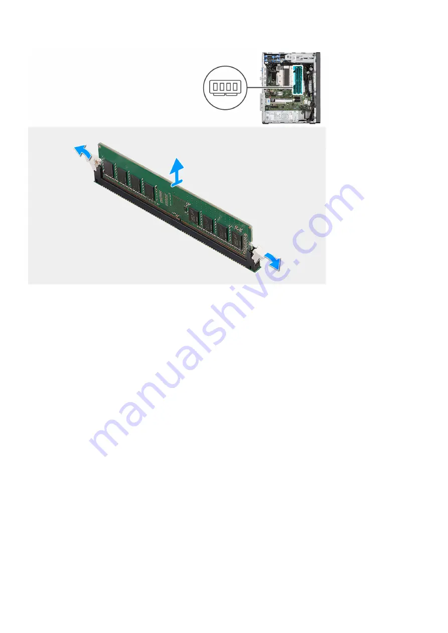
1. Pull the securing clips from both side of the memory module until the memory module pops up.
2. Slide and remove the memory module from the memory-module slot.

Installing the memory module

Prerequisites

If you are replacing a component, remove the existing component before performing the installation procedure.

About this task

The following image indicates the location of the memory module and provides a visual representation of the installation
procedure.

36

Removing and installing components

Содержание D31M

Страница 1: ...OptiPlex 7000 Tower Service Manual Regulatory Model D31M Regulatory Type D31M001 Mar 2022 Rev A00 ...

Страница 2: ...ential damage to hardware or loss of data and tells you how to avoid the problem WARNING A WARNING indicates a potential for property damage personal injury or death 2022 Dell Inc or its subsidiaries All rights reserved Dell EMC and other trademarks are trademarks of Dell Inc or its subsidiaries Other trademarks may be trademarks of their respective owners ...

Страница 3: ...ch hard drive assembly 18 Removing the 2 5 inch hard drive bracket 19 Installing the 2 5 inch hard drive bracket 20 Installing the secondary 2 5 inch hard drive assembly 21 Installing the primary 2 5 inch hard drive assembly 22 3 5 in hard drive assembly 23 Removing the 3 5 inch hard drive assembly 23 Removing the 3 5 inch hard drive bracket 24 Installing the 3 5 inch hard drive bracket 25 Install...

Страница 4: ...ing the power supply unit 56 Processor fan and heat sink assembly 59 Removing the processor fan and 125 W heat sink assembly 59 Removing the processor fan 60 Installing the processor fan 61 Installing the processor fan and 125 W heat sink assembly 62 Removing the processor fan and 65 W heat sink assembly 63 Installing the processor fan and 65 W heat sink assembly 64 Processor 65 Removing the proce...

Страница 5: ...Chapter 4 BIOS setup 105 Entering BIOS setup program 105 Navigation keys 105 One time boot menu 105 System setup options 106 Updating the BIOS 115 Updating the BIOS in Windows 115 Updating the BIOS in Linux and Ubuntu 115 Updating the BIOS using the USB drive in Windows 115 Updating the BIOS from the F12 One Time boot menu 116 System and setup password 117 Assigning a system setup password 117 Del...

Страница 6: ...Chapter 6 Getting help and contacting Dell 123 6 Contents ...

Страница 7: ...touching anything inside your computer ground yourself by touching an unpainted metal surface such as the metal at the back of the computer While you work periodically touch an unpainted metal surface to dissipate static electricity which could harm internal components CAUTION When you disconnect a cable pull it by its connector or its pull tab not the cable itself Some cables have connectors with...

Страница 8: ...t strap should be secure and in full contact with your skin and ensure that you remove all jewelry such as watches bracelets or rings prior to bonding yourself and the equipment Electrostatic discharge ESD protection ESD is a major concern when you handle electronic components especially sensitive components such as expansion cards processors memory DIMMs and system boards Very slight charges can ...

Страница 9: ...t once per week A wrist strap tester is the best method for doing this test If you do not have your own wrist strap tester check with your regional office to find out if they have one To perform the test plug the wrist strap s bonding wire into the tester while it is strapped to your wrist and push the button to test A green LED is lit if the test is successful a red LED is lit and an alarm sounds...

Страница 10: ...er working inside your computer About this task NOTE Leaving stray or loose screws inside your computer may severely damage your computer Steps 1 Replace all screws and ensure that no stray screws remain inside your computer 2 Connect any external devices peripherals or cables you removed before working on your computer 3 Replace any media cards discs or any other parts that you removed before wor...

Страница 11: ...box This is to ensure that the correct number of screws and correct screw type is restored when the component is replaced NOTE Some computers have magnetic surfaces Ensure that the screws are not left attached to such surfaces when replacing a component NOTE Screw color may vary with the configuration ordered Table 1 Screw list Component Screw type Quantity Screw image M 2 2230 2280 Solid state dr...

Страница 12: ...jor components of OptiPlex 7000 Tower 1 Side cover 2 3 5 inch hard disk drive 3 Slim ODD 4 Heat sink 5 WLAN card 6 Memory module 7 M 2 2280 solid state drive 8 Power button 9 System board 10 Front I O bracket 11 Front bezel 12 System chassis 13 System fan 14 Speaker 15 Intrusion switch 16 Power supply unit 12 Removing and installing components ...

Страница 13: ...t your Dell sales representative for purchase options Side cover Removing the side cover Prerequisites 1 Follow the procedure in before working inside your computer NOTE Ensure that you remove the security cable from the security cable slot if applicable About this task The following images indicate the location of the side cover and provide a visual representation of the removal procedure Removin...

Страница 14: ...er away from the chassis Installing the side cover Prerequisites If you are replacing a component remove the existing component before performing the installation procedure About this task The following image indicates the location of the side cover and provides a visual representation of the installation procedure 14 Removing and installing components ...

Страница 15: ...he chassis 2 Slide the side cover towards the front of the computer to install it 3 The release latch automatically locks the side cover to the chassis Next steps 1 Follow the procedure in after working inside your computer Removing and installing components 15 ...

Страница 16: ...the removal procedure Steps 1 Pry the retention tabs to release the front bezel from the computer 2 Slightly pull the front bezel and gently rotate to release the other tabs on the bezel from the slots in the computer chassis 3 Remove the front bezel from the computer Installing the front bezel Prerequisites If you are replacing a component remove the existing component before performing the insta...

Страница 17: ...icks into place Next steps 1 Install the side cover 2 Follow the procedure in after working inside your computer Hard drive assembly Removing the primary 2 5 inch hard drive assembly Prerequisites 1 Follow the procedure in before working inside your computer 2 Remove the side cover About this task The following images indicate the location of the 2 5 inch hard drive assembly and provide a visual r...

Страница 18: ...drive assembly from the computer NOTE Note the orientation of the hard drive so that you can replace it correctly Removing the secondary 2 5 inch hard drive assembly Prerequisites 1 Follow the procedure in before working inside your computer 2 Remove the side cover About this task The following images indicate the location of the 2 5 inch hard drive and provide a visual representation of the remov...

Страница 19: ...he release tabs on the hard drive bracket and slide the hard drive assembly out of the hard drive bracket 3 Lift the hard drive assembly from the computer NOTE The orientation of the hard drive so that you can replace it correctly Removing the 2 5 inch hard drive bracket Prerequisites 1 Follow the procedure in before working inside your computer 2 Remove the side cover 3 Remove the 2 5 inch primar...

Страница 20: ... of the bracket NOTE The orientation or the SATA connector marking on the hard drive so that you can replace it correctly Installing the 2 5 inch hard drive bracket Prerequisites If you are replacing a component remove the existing component before performing the installation procedure About this task The following image indicates the location of the 2 5 inch hard drive bracket and provides a visu...

Страница 21: ...ard drive or 2 5 inch secondary hard drive 2 Install the side cover 3 Follow the procedure in after working inside your computer Installing the secondary 2 5 inch hard drive assembly Prerequisites If you are replacing a component remove the existing component before performing the installation procedure About this task The following image indicates the location of the 2 5 inch hard drive assembly ...

Страница 22: ...nstall the side cover 2 Follow the procedure in after working inside your computer Installing the primary 2 5 inch hard drive assembly Prerequisites If you are replacing a component remove the existing component before performing the installation procedure About this task The following image indicates the location of the 2 5 inch hard drive assembly and provides a visual representation of the inst...

Страница 23: ...t steps 1 Install the 2 5 inch primary hard drive or 2 5 inch secondary hard drive 2 Install the side cover 3 Follow the procedure in after working inside your computer 3 5 in hard drive assembly Removing the 3 5 inch hard drive assembly Prerequisites 1 Follow the procedure in before working inside your computer 2 Remove the side cover 3 Remove the front bezel Removing and installing components 23...

Страница 24: ...d drive module 2 Push the securing tab to release the hard drive assembly from the chassis 3 Remove the EMI shield from the front side of the chassis 4 Slide the hard drive assembly away from the chassis Removing the 3 5 inch hard drive bracket Prerequisites 1 Follow the procedure in before working inside your computer 2 Remove the side cover 3 Remove the 3 5 inch hard drive assembly 24 Removing a...

Страница 25: ...ts on the hard drive 2 Lift at an angle and remove the hard drive off the hard drive bracket Installing the 3 5 inch hard drive bracket Prerequisites If you are replacing a component remove the existing component before performing the installation procedure About this task The following image indicates the location of the 3 5 inch hard drive bracket and provides a visual representation of the inst...

Страница 26: ...he side cover 3 Follow the procedure in after working inside your computer Installing the 3 5 inch hard drive assembly Prerequisites If you are replacing a component remove the existing component before performing the installation procedure About this task The following image indicates the location of the 3 5 inch hard drive assembly and provides a visual representation of the installation procedu...

Страница 27: ...rive assembly with the tabs on the chassis 4 Route the power cable and the data cable through the routing guides on the hard drive assembly and connect the cables to the hard drive Next steps 1 Install the front bezel 2 Install the side cover 3 Follow the procedure in after working inside your computer Removing and installing components 27 ...

Страница 28: ...e screw M2x3 5 that secures the solid state drive to the system board 2 Slide at an angle to lift and remove the solid state drive from its connector on the system board Installing the M 2 2230 PCIe solid state drive Prerequisites If you are replacing a component remove the existing component before performing the installation procedure About this task The following image indicates the location of...

Страница 29: ... drive to the system board Next steps 1 Install the side cover 2 Follow the procedure in after working inside your computer Removing the M 2 2280 PCIe solid state drive Prerequisites 1 Follow the procedure in before working inside your computer 2 Remove the side cover About this task The following images indicate the location of the solid state drive and provide a visual representation of the remo...

Страница 30: ... procedure for removing the other solid state drive Installing the M 2 2280 PCIe solid state drive Prerequisites If you are replacing a component remove the existing component before performing the installation procedure About this task The following image indicates the location of the solid state drive and provides a visual representation of the installation procedure 30 Removing and installing c...

Страница 31: ...board NOTE Repeat the above procedure for installing the other solid state drive Next steps 1 Install the side cover 2 Follow the procedure in after working inside your computer WLAN card Removing the WLAN card Prerequisites 1 Follow the procedure in before working inside your computer 2 Remove the side cover About this task The following images indicate the location of the wireless card and provi...

Страница 32: ...nd remove the WLAN card from the connector on the system board Installing the WLAN card Prerequisites If you are replacing a component remove the existing component before performing the installation procedure About this task The following image indicates the location of the wireless card and provides a visual representation of the installation procedure 32 Removing and installing components ...

Страница 33: ...ard Antenna cable color Main white triangle White Auxiliary black triangle Black 2 Place the WLAN card bracket to secure the WLAN antenna cables 3 Insert the WLAN card into the connector on the system board 4 Replace the M2x3 5 screw to secure the plastic tab to the WLAN card Next steps 1 Install the side cover 2 Follow the procedure in after working inside your computer Removing and installing co...

Страница 34: ...teps 1 Using a plastic scribe gently pry the coin cell battery out of the slot on the system board 2 Remove the coin cell battery away from the computer Installing the coin cell battery Prerequisites If you are replacing a component remove the existing component before performing the installation procedure About this task The following image indicates the location of the coin cell battery and prov...

Страница 35: ...eps 1 Install the side cover 2 Follow the procedure in after working inside your computer Memory module Removing the memory module Prerequisites 1 Follow the procedure in before working inside your computer 2 Remove the side cover About this task The following images indicate the location of the memory module and provide a visual representation of the removal procedure Removing and installing comp...

Страница 36: ...ory module slot Installing the memory module Prerequisites If you are replacing a component remove the existing component before performing the installation procedure About this task The following image indicates the location of the memory module and provides a visual representation of the installation procedure 36 Removing and installing components ...

Страница 37: ...y module and reinstall it Next steps 1 Install the side cover 2 Follow the procedure in after working inside your computer Expansion card Removing the graphics card Prerequisites 1 Follow the procedure in before working inside your computer 2 Remove the side cover About this task The following images indicate the location of the graphics card and provide a visual representation of the removal proc...

Страница 38: ...hics card slot Installing the graphics card Prerequisites If you are replacing a component remove the existing component before performing the installation procedure About this task The following images indicate the location of the graphics card and provide a visual representation of the installation procedure 38 Removing and installing components ...

Страница 39: ... press down firmly Ensure that the card is firmly seated 3 Lift the pull tab to close the PCIe door Next steps 1 Install the side cover 2 Follow the procedure in after working inside your computer Removing optional SMA module Prerequisites 1 Follow the procedure in before working inside your computer 2 Remove the side cover Removing and installing components 39 ...

Страница 40: ...d remove the SMA module from its connector on the system board Installing optional SMA module Prerequisites If you are replacing a component remove the existing component before performing the installation procedure About this task The following images indicate the location of the optional SMA module and provide a visual representation of the installation procedure 40 Removing and installing compo...

Страница 41: ...bracket to release it and then lift the bracket out of the system 2 Lift the pull tab to open the PCIe door 3 Insert the optional SMA module into its slot on the system board Next steps 1 Install the side cover 2 Follow the procedure in after working inside your computer Removing and installing components 41 ...

Страница 42: ...procedure in before working inside your computer 2 Remove the side cover About this task The following images indicate the location of the optional powered add in card and provide a visual representation of the removal procedure 42 Removing and installing components ...

Страница 43: ...en the PCIe door 2 Disconnect the 6 pin power cable from its connector on the powered add in card 3 Hold and remove the powered add in card from its slot on the system board 4 Close the PCIe door Removing and installing components 43 ...

Страница 44: ...mponent remove the existing component before performing the installation procedure About this task The following images indicate the location of the optional powered add in card and provide a visual representation of the installation procedure 44 Removing and installing components ...

Страница 45: ...ull tab to open the PCIe door 2 Connect the 6 pin power cable to the connector on the powered add in card 3 Insert the optional powered add in card into its slot on the system board Removing and installing components 45 ...

Страница 46: ... computer Graphical processing unit Removing the powered GPU Prerequisites 1 Follow the procedure in before working inside your computer 2 Remove the side cover About this task The following images indicate the location of the powered graphical processing unit and provide a visual representation of the removal procedure 46 Removing and installing components ...

Страница 47: ...ab to open the PCIe door 5 Push and hold the securing tab on the graphics card slot and lift the powered GPU away from the graphics card slot 6 Close the PCIe door Installing the powered GPU Prerequisites If you are replacing a component remove the existing component before performing the installation procedure About this task The following images indicate the location of the powered graphical pro...

Страница 48: ... Align the powered GPU with the PCI Express card connector on the system board 3 Using the alignment post connect the powered GPU in the connector and press down firmly Ensure that the powered GPU is firmly seated 48 Removing and installing components ...

Страница 49: ...s through the slot on the cable holder to the connector on the powered GPU Next steps 1 Install the side cover 2 Follow the procedure in after working inside your computer Slim optical drive Removing the Slim optical drive Prerequisites 1 Follow the procedure in before working inside your computer 2 Remove the side cover About this task The following images indicate the location of the slim ODD an...

Страница 50: ... ODD from the ODD slot Installing the Slim optical drive Prerequisites If you are replacing a component remove the existing component before performing the installation procedure About this task The following images indicate the location of the slim ODD and provide a visual representation of the installation procedure 50 Removing and installing components ...

Страница 51: ...ough the routing guides and connect the cables to the slim ODD Next steps 1 Install the side cover 2 Follow the procedure in after working inside your computer Slim optical drive bracket Removing the slim ODD bracket Prerequisites 1 Follow the procedure in before working inside your computer 2 Remove the side cover Removing and installing components 51 ...

Страница 52: ...ODD bracket off the ODD Installing the slim ODD bracket Prerequisites If you are replacing a component remove the existing component before performing the installation procedure About this task The following images indicate the location of the slim ODD bracket and provide a visual representation of the installation procedure Steps 1 Align and place the slim ODD bracket on the ODD slots 2 Snap the ...

Страница 53: ...provide a visual representation of the removal procedure Steps 1 Disconnect the speaker cable from the connector on the system board 2 Press the tab and slide the speaker along with the cable from the slot on the chassis Installing the speaker Prerequisites If you are replacing a component remove the existing component before performing the installation procedure About this task The following imag...

Страница 54: ...pply unit Removing the power supply unit Prerequisites 1 Follow the procedure in before working inside your computer 2 Remove the side cover NOTE Note the routing of all cables as you remove them so that you can route them correctly while you are replacing the power supply unit About this task The following images indicate the location of the power supply unit and provide a visual representation o...

Страница 55: ...Removing and installing components 55 ...

Страница 56: ...Lift the power supply unit off the chassis Installing the power supply unit Prerequisites If you are replacing a component remove the existing component before performing the installation procedure WARNING The cables and ports on the back of the power supply unit are color coded to indicate the different power wattage Ensure that you plug in the cable to the correct port Failure to do so may resul...

Страница 57: ...About this task The following images indicate the location of the power supply unit and provide a visual representation of the installation procedure Removing and installing components 57 ...

Страница 58: ...58 Removing and installing components ...

Страница 59: ...the processor fan and 125 W heat sink assembly Prerequisites 1 Follow the procedure in before working inside your computer WARNING The heat sink may become hot during normal operation Allow sufficient time for the heat sink to cool before you touch it CAUTION For maximum cooling of the processor do not touch the heat transfer areas on the heat sink The oils in your skin can reduce the heat transfe...

Страница 60: ...d 3 Lift the processor fan and heat sink assembly from the system board Removing the processor fan Prerequisites 1 Follow the procedure in before working inside your computer 2 Remove the side cover 3 Remove the processor fan and heat sink assembly About this task The following images indicate the location of the processor fan and provide a visual representation of the removal procedure 60 Removin...

Страница 61: ...k Installing the processor fan Prerequisites If you are replacing a component remove the existing component before performing the installation procedure About this task The following images indicate the location of the processor fan and provide a visual representation of the removal procedure Removing and installing components 61 ...

Страница 62: ... installation procedure NOTE If either the processor or the heat sink is replaced use the thermal grease that is provided in the kit to ensure that thermal conductivity is achieved About this task The following image indicates the location of the processor fan and 125 W heat sink and provides a visual representation of the installation procedure Steps 1 Align the screws on the processor fan and he...

Страница 63: ... W heat sink assembly Prerequisites 1 Follow the procedure in before working inside your computer WARNING The heat sink may become hot during normal operation Allow sufficient time for the heat sink to cool before you touch it CAUTION For maximum cooling of the processor do not touch the heat transfer areas on the heat sink The oils in your skin can reduce the heat transfer capability of the therm...

Страница 64: ...ensure that thermal conductivity is achieved About this task The following image indicates the location of the processor fan and heat sink assembly and provides a visual representation of the installation procedure Steps 1 Align the screw holes on the processor fan and heat sink assembly with the screw holes on the system board 2 Tighten the four captive screws that secure the processor fan and he...

Страница 65: ...edure Steps 1 Press down and push the release lever away from the processor to release it from the securing tab 2 Lift the lever upward to lift the processor cover CAUTION When removing the processor do not touch any of the pins inside the socket or allow any objects to fall on the pins in the socket 3 Gently lift the processor from the processor socket Installing the processor Prerequisites If yo...

Страница 66: ...thers the processor is not seated properly 3 When the processor is fully seated in the socket pivot the release lever down and place it under the tab on the processor cover Next steps 1 Install the processor fan and 125 W heat sink assembly or processor fan and heat sink assembly 2 Install the side cover 3 Follow the procedure in after working inside your computer Communication card Removing the c...

Страница 67: ...the communication card from the system board 5 Close the PCIe door Installing the communication card Prerequisites If you are replacing a component remove the existing component before performing the installation procedure About this task The following image indicates the location of the communication card and provides a visual representation of the installation procedure Removing and installing c...

Страница 68: ...oor 3 Route the communication card cable using the routing guides 4 Connect the communication card cable to its connector on the system board 5 Close the PCIe door Next steps 1 Install the side cover 2 Follow the procedure in after working inside your computer 68 Removing and installing components ...

Страница 69: ...ng image indicates the location of the chassis fan and provide a visual representation of the removal procedure Steps 1 Disconnect the fan cable from the connector on the system board 2 Locate the position of rubber grommets 3 Gently pull the rubber grommets to release the fan from the chassis 4 Remove the fan off the chassis Removing and installing components 69 ...

Страница 70: ...of the installation procedure Steps 1 Insert the rubber grommets on the chassis 2 Align the slots on the fan with the rubber grommets on the chassis 3 Route the rubber grommets through the slots on the fan and pull the rubber grommets until the fan snaps into position 4 Connect the fan cable to the connector on the system board Next steps 1 Install the side cover 2 Follow the procedure in after wo...

Страница 71: ... grease 2 Remove the side cover About this task The following image indicates the location of the VR heat sink and provide a visual representation of the removal procedure Steps 1 Loosen the two captive screws that secure the VR heat sink to the system board 2 Lift the VR heat sink off the system board Installing the VR heat sink Prerequisites If you are replacing a component remove the existing c...

Страница 72: ...e side cover 2 Follow the procedure in after working inside your computer Power button Removing the power button Prerequisites 1 Follow the procedure in before working inside your computer 2 Remove the side cover 3 Remove the front bezel About this task The following images indicate the location of the power button and provide a visual representation of the removal procedure 72 Removing and instal...

Страница 73: ... connector on the system board 2 Press the release tabs on the power button head and slide the power button cable out from the front side chassis of the computer 3 Pull the power button cable out from the computer Removing and installing components 73 ...

Страница 74: ...representation of the installation procedure Steps 1 Insert the power button cable into the slot from the front side of the computer and press the power button head until it clicks into the place in the chassis 2 Align and connect the power button cable to the connector on the system board Next steps 1 Install the front bezel 2 Install the side cover 3 Follow the procedure in after working inside ...

Страница 75: ...rocedure Steps 1 Disconnect the intruder cable from the connector on the system board 2 Slide and remove the intrusion switch from the chassis Installing the intrusion switch Prerequisites If you are replacing a component remove the existing component before performing the installation procedure About this task The following image indicates the location of the intrusion switch and provides a visua...

Страница 76: ... the procedure in after working inside your computer SD card reader optional Removing the SD card reader Prerequisites 1 Follow the procedure in before working inside your computer 2 Remove the side cover 3 Remove the front bezel About this task The following image indicates the location of the SD card reader and provides a visual representation of the removal procedure 76 Removing and installing ...

Страница 77: ...der from the system chassis Installing the SD card reader Prerequisites If you are replacing a component remove the existing component before performing the installation procedure About this task The following image indicates the location of the SD card reader and provides a visual representation of the installation procedure Removing and installing components 77 ...

Страница 78: ...de cover 3 Follow the procedure in after working inside your computer Optional modules Removing optional DisplayPort module Prerequisites 1 Follow the procedure in before working inside your computer 2 Remove the side cover 3 Remove the front bezel About this task The following images indicate the location of the optional DisplayPort module and provide a visual representation of the removal proced...

Страница 79: ...e DisplayPort module from the computer Installing optional DisplayPort module Prerequisites If you are replacing a component remove the existing component before performing the installation procedure About this task The following images indicate the location of the optional DisplayPort module and provide a visual representation of the installation procedure Removing and installing components 79 ...

Страница 80: ...ptional DisplayPort module to the system Next steps 1 Install the front bezel 2 Install the side cover 3 Follow the procedure in after working inside your computer Removing optional VGA module Prerequisites 1 Follow the procedure in before working inside your computer 2 Remove the side cover 3 Remove the front bezel About this task The following images indicate the location of the optional VGA mod...

Страница 81: ...t before performing the installation procedure About this task The following images indicate the location of the optional VGA module and provide a visual representation of the installation procedure Steps 1 To remove the dummy metal bracket insert a flat head screwdriver in the hole of the bracket push the bracket to release the bracket and then lift the bracket out from the system Removing and in...

Страница 82: ...emoving optional HDMI module Prerequisites 1 Follow the procedure in before working inside your computer 2 Remove the side cover 3 Remove the front bezel About this task The following images indicate the location of the optional HDMI module and provide a visual representation of the removal procedure Steps 1 Remove the two M3X3 screws that secure the optional HDMI module to the computer chassis 2 ...

Страница 83: ... the installation procedure Steps 1 To remove the dummy metal bracket insert a flat head screwdriver in the hole of the bracket push the bracket to release the bracket and then lift the bracket out from the system 2 Insert the optional HDMI module into its slot from the inside of your computer 3 Connect the HDMI module cable to the connector on the system board 4 Replace the two M3X3 screws to sec...

Страница 84: ...icate the location of the optional Serial module and provide a visual representation of the removal procedure Steps 1 Remove the two M3X3 screws that secure the optional Serial module to the computer chassis 2 Disconnect the Serial module cable from the connector on the system board 3 Remove the Serial module from the computer Installing optional Serial module Prerequisites If you are replacing a ...

Страница 85: ...cket to release the bracket and then lift the bracket out from the system 2 Insert the optional Serial module into its slot from the inside of your computer 3 Connect the Serial module cable to the connector on the system board 4 Replace the two M3X3 screws to secure the optional Serial module to the system Next steps 1 Install the front bezel 2 Install the side cover 3 Follow the procedure in aft...

Страница 86: ...crews that secure the optional Type C module to the computer chassis 2 Disconnect the Type C module cable from the connector on the system board 3 Remove the Type C module from the computer Installing optional Type C module Prerequisites If you are replacing a component remove the existing component before performing the installation procedure About this task The following images indicate the loca...

Страница 87: ...sert the optional Type C module into its slot from the inside of your computer 3 Connect the Type C module cable to the connector on the system board 4 Replace the two M3X3 screws to secure the optional Type C module to the system Next steps 1 Install the front bezel 2 Install the side cover 3 Follow the procedure in after working inside your computer Removing and installing components 87 ...

Страница 88: ...procedure in before working inside your computer 2 Remove the side cover About this task The following images indicate the location of the optional Thunderbolt 4 module and provide a visual representation of the removal procedure 88 Removing and installing components ...

Страница 89: ...Steps 1 Lift the pull tab to open the PCIe door 2 Hold and remove the Thunderbolt 4 module from its slot on the system board 3 Close the PCIe door Removing and installing components 89 ...

Страница 90: ...ponent remove the existing component before performing the installation procedure About this task The following images indicate the location of the optional Thunderbolt 4 module and provide a visual representation of the installation procedure 90 Removing and installing components ...

Страница 91: ...Steps 1 Lift the pull tab to open the PCIe door 2 Insert the optional Thunderbolt 4 module into its slot on the system board 3 Close the PCIe door Removing and installing components 91 ...

Страница 92: ...ary antennas to the system chassis 2 Disconnect the antenna cables from the WLAN card 3 Unroute the antennas through the routing guides and remove the antenna cables using the hole that is provided in the system chassis 4 Hold and remove the main and auxiliary antennas from the system chassis Installing internal antenna Prerequisites If you are replacing a component remove the existing component b...

Страница 93: ...ess card Antenna cable color Main white triangle White Auxiliary black triangle Black Next steps 1 Install the side cover 2 Follow the procedure in after working inside your computer System board Removing the system board Prerequisites 1 Follow the procedure in before working inside your computer NOTE Your computer s Service Tag is stored in the system board You must enter the Service Tag in the B...

Страница 94: ... if the system is configured with powered GPU 10 Remove the speaker 11 Remove the intrusion switch 12 Remove the VR heatsink 13 Remove the processor fan and 125 W heat sink assembly or processor fan and heat sink assembly 14 Remove the chassis fan 15 Remove the processor About this task The following image indicates the connectors on your system board 1 ATX CPU power connector 2 ATX CPU power conn...

Страница 95: ... 16 Thunderbolt header 17 PCIe x4 Slot4 18 PCI Slot3 19 PCIe x16 Slot2 20 PCIe x1 Slot1 21 System fan connector 22 Chassis Intrusion Detection connector 23 Type C connector 24 Processor socket The following images indicate the location of the system board and provide a visual representation of the removal procedure Removing and installing components 95 ...

Страница 96: ...96 Removing and installing components ...

Страница 97: ...I O bracket to the chassis 2 Slide and remove the front I O bracket from the chassis 3 Disconnect the power and HDD cables that are connected to the system board and unroute them from the routing guides on the chassis Removing and installing components 97 ...

Страница 98: ...nt before performing the installation procedure About this task The following image indicates the connectors on your system board 1 ATX CPU power connector 2 ATX CPU power connector 3 Memory module connectors 4 Power button connector 5 SD card reader connector 6 M 2 PCIe SSD connector 7 M 2 PCIe SSD connector 8 SATA0 connector blue 9 Two SATA1 2 connector black 10 SATA3 connector white 11 SATA pow...

Страница 99: ... System fan connector 22 Chassis Intrusion Detection connector 23 Type C connector 24 Processor socket The following images indicate the location of the system board and provide a visual representation of the installation procedure Removing and installing components 99 ...

Страница 100: ...100 Removing and installing components ...

Страница 101: ...Removing and installing components 101 ...

Страница 102: ...ront I O bracket to the chassis Next steps 1 Install the processor 2 Install the chassis fan 3 Install the processor fan and 125 W heat sink assembly or processor fan and heat sink assembly 4 Install the coin cell battery 5 Install the VR heatsink 6 Remove the intrusion switch 7 Remove the speaker 8 Install the powered GPU NOTE This step is required only if the system is configured with powered GP...

Страница 103: ... the system board removes any changes that you have made to the BIOS using the BIOS setup program You must make the appropriate changes again after you replace the system board Removing and installing components 103 ...

Страница 104: ...ivers and downloads When troubleshooting downloading or installing drivers it is recommended that you read the Dell Knowledge Based article Drivers and Downloads FAQ 000123347 3 104 Drivers and downloads ...

Страница 105: ...ing base devices Entering BIOS setup program About this task Turn on or restart your computer and press F2 immediately Navigation keys NOTE For most of the System Setup options changes that you make are recorded but do not take effect until you restart the system Table 4 Navigation keys Keys Navigation Up arrow Moves to the previous field Down arrow Moves to the next field Enter Selects a value in...

Страница 106: ...p Tag Displays the Ownership Tag of the computer Signed Firmware Update Displays whether the Signed Firmware Update is enabled on your computer Processor Information Processor Type Displays the processor type Maximum Clock Speed Displays the maximum processor clock speed Minimum Clock Speed Displays the minimum processor clock speed Current Clock Speed Displays the current processor clock speed Co...

Страница 107: ...ard drive information of the computer Slot 2 Displays the SATA hard drive information of the computer Slot 3 Displays the SATA hard drive information of the computer Slot 4 Displays the SATA hard drive information of the computer Table 6 System setup options Boot Configuration menu Boot Configuration Boot Sequence Boot Mode UEFI only Displays the boot mode Boot Sequence Displays the boot sequence ...

Страница 108: ...he option is enabled Dust Filter Maintenance Enable or disable the dust filter maintenance By default the Disabled option is enabled Table 8 System setup options Storage menu Storage SATA Operation Enable or disable the operating mode of the integrated SATA hard drive controller By default the AHCIoption is enabled Storage Interface Port Enablement Enable or disable the onboard drives By default a...

Страница 109: ...Digital SD Card Read Only Mode option is not enabled Table 9 System setup options Display menu Display Multi Display Enable Multi Display Enable or disable the Enable Multi Display buttons on the computer By default the option is enabled Primary Display Video Primary Display Determines the primary display when multiple controllers are available on the computer By default the Auto option is enabled...

Страница 110: ... default the Power Off option is enabled Active State Power Management Aspm Enables or disables the Active State Power Management ASPM level By default the Auto option is enabled Block Sleep Enables to block entering sleep S3 mode in the operating system By default the Block Sleep option is disabled Deep Sleep Control Enable or disable the Deep Sleep mode support By default the Disabled option is ...

Страница 111: ...e Enable or disable or permanently disable the BIOS module interface of the optional Absolute Persistence Module service from Absolute software By default the Enable Absolute option is enabled UEFI Boot Path Security Controls whether or not the computer will prompt the user to enter the admin password if set when booting to a UEFI boot device from the F12 boot menu By default the Always Except Int...

Страница 112: ...System setup options Update Recovery menu Update Recovery UEFI Capsule Firmware Updates Enable or disable BIOS updates through UEFI capsule update packages By default the option is enabled BIOS Recovery from Hard Drive Enables the user to recover from certain corrupted BIOS conditions from a recovery file on the user primary hard drive or an external USB key By default the option is enabled BIOS D...

Страница 113: ...isable the Intel AMT provisioning using the local provisioning file through a USB storage device By default the option is disabled SERR Messages Enable or disable SERR messages By default the option is enabled Table 16 System setup options Keyboard menu Keyboard Keyboard Errors Enable Keyboard Error Detection Enable or disable the keyboard error detection By default the option is enabled Numlock L...

Страница 114: ...by Intel Trusted Execution Technology By default the option is disabled Table 19 System setup options Performance menu Performance Multi Core Support Active Cores Enables to change the number of CPU cores available to the operating system By default the All Cores options are enabled Intel SpeedStep Enable Intel SpeedStep Technology Enables the computer to dynamically adjust processor voltage and c...

Страница 115: ...BIOS file for your computer 7 After the download is complete browse the folder where you saved the BIOS update file 8 Double click the BIOS update file icon and follow the on screen instructions For more information see knowledge base article 000124211 at www dell com support Updating the BIOS in Linux and Ubuntu To update the system BIOS on a computer that is installed with Linux or Ubuntu see th...

Страница 116: ...enu to see if BIOS FLASH UPDATE is listed as a boot option for your computer If the option is listed then the BIOS supports this BIOS update option NOTE Only computers with BIOS Flash Update option in the F12 One Time boot menu can use this function Updating from the One Time boot menu To update your BIOS from the F12 One Time boot menu you need the following USB drive formatted to the FAT32 file ...

Страница 117: ...stem BIOS or System Setup screen select Security and press Enter The Security screen is displayed 2 Select System Admin Password and create a password in the Enter the new password field Use the following guidelines to assign the system password A password can have up to 32 characters At least one special character _ Numbers 0 through 9 Upper case letters from A to Z Lower case letters from a to z...

Страница 118: ...rompts you to save the changes 6 Press Y to save the changes and exit from System Setup The computer restarts Clearing CMOS settings About this task CAUTION Clearing CMOS settings reset the BIOS settings on your computer Steps 1 Remove the side cover 2 Disconnect the battery cable from the system board 3 Remove the coin cell battery 4 Wait for one minute 5 Replace the coin cell battery 6 Connect t...

Страница 119: ...esent at the computer terminal when the diagnostic tests are performed For more information see https www dell com support kbdoc 000180971 Running the SupportAssist Pre Boot System Performance Check Steps 1 Turn on your computer 2 As the computer boots press the F12 key as the Dell logo appears 3 On the boot menu screen select the Diagnostics option 4 Click the arrow at the bottom left corner Diag...

Страница 120: ...lid memory installed Reset the memory module If problem persists replace the memory module 2 6 System board Chipset Error Clock failure Gate A20 failure Super I O failure Keyboard controller failure Flash latest BIOS version If problem persists replace the system board 3 1 CMOS battery failure Reset the CMOS battery connection If problem persists replace the RTS battery 3 2 PCI or Video card chip ...

Страница 121: ...tAssist OS Recovery User s Guide at www dell com serviceabilitytools Click SupportAssist and then click SupportAssist OS Recovery Real Time Clock RTC reset The Real Time Clock RTC reset function allows you or the service technician to recover the recently launched model Dell Latitude and Precision systems from No POST No Boot No Power situations You can initiate the RTC reset on the system from a ...

Страница 122: ...ycle About this task If your computer is unable to access the internet due to WiFi connectivity issues a WiFi power cycle procedure may be performed The following procedure provides the instructions on how to conduct a WiFi power cycle NOTE Some ISPs Internet Service Providers provide a modem router combo device Steps 1 Turn off your computer 2 Turn off the modem 3 Turn off the wireless router 4 W...

Страница 123: ...Service Tag or Express Service Code at www dell com support For more information on how to find the Service Tag for your computer see Locate the Service Tag on your computer Dell knowledge base articles for a variety of computer concerns 1 Go to www dell com support 2 On the menu bar at the top of the Support page select Support Knowledge Base 3 In the Search field on the Knowledge Base page type ...

Отзывы: