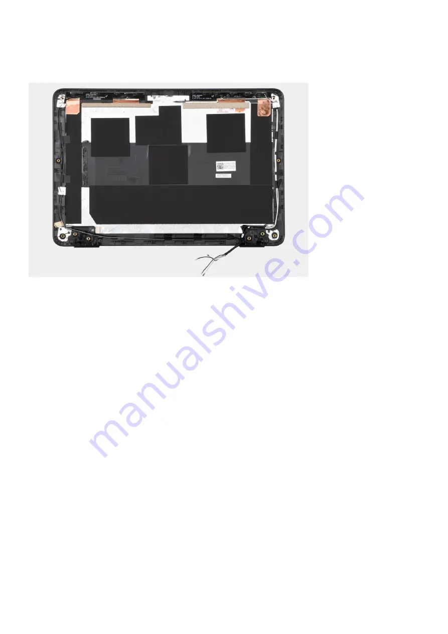
background image

About this task

The following image indicates the location of the coin-cell battery and provides a visual representation of the installation
procedure.

Steps

Place the display back-cover on a flat surface and perform the following steps to install the display back cover.

Next steps

1. Install the 

display cable

.

2. Install the 

camera

.

3. Install the 

display hinges

.

4. Install the 

display panel

.

5. Install the 

display bezel

.

6. Install the 

display assembly

.

7. Install the 

WWAN card

 for 4G LTE enabled systems.

8. Install the 

base cover

.

9. Follow the procedure in 

after working inside your computer

.

Palmrest assembly

Installing the palmrest assembly

Prerequisites

If you are replacing a component, remove the existing component before performing the installation procedure.

About this task

The following image indicates the location of the palmrest assembly and provides a visual representation of the installation
procedure.

58

Removing and installing components

Содержание Chromebook 3100

Страница 1: ...Dell Chromebook 3100 Service Manual Regulatory Model P29T Regulatory Type P29T001 March 2021 Rev A03 ...

Страница 2: ...ential damage to hardware or loss of data and tells you how to avoid the problem WARNING A WARNING indicates a potential for property damage personal injury or death 2021 Dell Inc or its subsidiaries All rights reserved Dell EMC and other trademarks are trademarks of Dell Inc or its subsidiaries Other trademarks may be trademarks of their respective owners ...

Страница 3: ...ools 10 Screw list 10 Major components of your system 12 Disassembly and reassembly 13 Base cover 13 SIM card 17 WWAN card 19 Battery 21 Keyboard 25 Display assembly 28 Input Output board 31 System board 34 Speaker 40 Display bezel 42 Display panel 46 Camera 50 Display hinges 52 Display cable 55 Display back cover 57 Palmrest assembly 58 Chapter 3 Technology and components 61 USB features 61 USB T...

Страница 4: ... 73 Chrome commands 75 Commonly used CROSH command 81 Check battery charging status 81 Reset Chromebook 88 Recovery Chromebook 91 Recovering the Chromebook 91 Chapter 5 Getting help and contacting Dell 94 4 Contents ...

Страница 5: ...n surface to avoid scratches on the display 7 Place the computer face down Safety precautions The safety precautions chapter details the primary steps to be taken before performing any disassembly instructions Observe the following safety precautions before you perform any installation or break fix procedures involving disassembly or reassembly Turn off the system and all attached peripherals Disc...

Страница 6: ...iately produce outward symptoms related to the damage The weakened trace may take weeks or months to melt and in the meantime may cause degradation of memory integrity intermittent memory errors etc The more difficult type of damage to recognize and troubleshoot is the intermittent also called latent or walking wounded failure Perform the following steps to prevent ESD damage Use a wired ESD wrist...

Страница 7: ...ng All ESD sensitive devices must be shipped and received in static safe packaging Metal static shielded bags are preferred However you should always return the damaged part using the same ESD bag and packaging that the new part arrived in The ESD bag should be folded over and taped shut and all the same foam packing material should be used in the original box that the new part arrived in ESD sens...

Страница 8: ...self Some cables have connectors with locking tabs if you are disconnecting this type of cable press in on the locking tabs before you disconnect the cable As you pull connectors apart keep them evenly aligned to avoid bending any connector pins Also before you connect a cable ensure that both connectors are correctly oriented and aligned NOTE Disconnect all power sources before opening the comput...

Страница 9: ...ure that no stray screws remain inside your computer 2 Connect any external devices peripherals or cables you removed before working on your computer 3 Replace any media cards discs or any other parts that you removed before working on your computer 4 Connect your computer and all attached devices to their electrical outlets 5 Turn on your computer Working on your computer 9 ...

Страница 10: ...be Recommended for field technician Screw list The table provides the list of screws that are used for securing different components Table 1 Screw list Component Screw type Quantity Screw image Base cover 9 NOTE Screw color may vary depending on the configuration ordered Battery M2x4 3 Input Output bracket M2x4 2 Input Output board M2x4 2 For WiFi enabled systems 3 For 4G LTE enabled systems Syste...

Страница 11: ...t Component Screw type Quantity Screw image Wireless card bracket M2x3 1 Display cable bracket M2x4 1 Display bezel M2 5x3 8 4 Display panel M2x3 4 Display hinges M2 5x2 5 M2x3 4 2 Removing and installing components 11 ...

Страница 12: ...Major components of your system 1 Base cover 2 System board 3 Battery 4 Speaker 5 Palmrest assembly 6 Display assembly 12 Removing and installing components ...

Страница 13: ...esentative for purchase options Disassembly and reassembly NOTE The images in this document may differ from your computer depending on the configuration you ordered Base cover Removing the base cover Prerequisites Follow the procedure in before working inside your computer About this task The following images indicate the location of the base cover and provide a visual representation of the remova...

Страница 14: ... shaped indents at the top side of the base cover and then working along the sides NOTE While removing the base cover on site technicians must take care to remove the base cover carefully There are prying recess points next to the left and right hinges which ease the disassembly procedure With the help of a plastic scribe 14 Removing and installing components ...

Страница 15: ...omputer chassis 4 Disconnect the battery cable from the connector on the system board Installing the base cover Prerequisites If you are replacing a component remove the existing component before performing the installation procedure About this task The following images indicate the location of the base cover and provide a visual representation of the installation procedure Removing and installing...

Страница 16: ...16 Removing and installing components ...

Страница 17: ...er SIM card Removing the SIM card Prerequisites 1 Follow the procedure in before working inside your computer 2 Remove the base cover About this task NOTE The following steps are applicable only for 4G LTE enabled systems NOTE The following steps are not applicable for systems configured with pre installed SIM card WARNING Do not press on the SIM card connector The following image indicates the lo...

Страница 18: ...nabled systems NOTE The following steps are not applicable for systems configured with pre installed SIM card WARNING Do not press on the SIM card connector If you are replacing a component remove the existing component before performing the installation procedure The following image indicates the location of the SIM card and provides a visual representation of the installation procedure 18 Removi...

Страница 19: ...refer Connect to a mobile data network Next steps 1 Install the base cover 2 Follow the procedure in after working inside your computer WWAN card Removing the WWAN card Prerequisites NOTE The following steps are applicable only for 4G LTE enabled systems 1 Follow the procedure in before working inside your computer 2 Remove the base cover About this task The following image indicates the location ...

Страница 20: ... its slot on the system board 5 Lift and remove the WWAN card from the system board Installing the WWAN card Prerequisites NOTE The following steps are applicable only for 4G LTE enabled systems If you are replacing a component remove the existing component before performing the installation procedure About this task The following image indicates the location of the WWAN card and provides a visual...

Страница 21: ...se cover 2 Follow the procedure in after working inside your computer Battery Lithium ion battery precautions CAUTION Exercise caution when handling Lithium ion batteries Discharge the battery completely before removing it Disconnect the AC power adapter from the system and operate the computer solely on battery power the battery is fully discharged when the computer no longer turns on when the po...

Страница 22: ...ncturing bending or crushing a lithium ion battery can be dangerous In such an instance contact Dell technical support for assistance See www dell com contactdell Always purchase genuine batteries from www dell com or authorized Dell partners and resellers Removing the battery Prerequisites 1 Follow the procedure in before working inside your computer 2 Remove the base cover NOTE If the battery is...

Страница 23: ...ve tape upward to release the battery from the double sided sticker that secures the battery to the palmrest assembly CAUTION Do not pull outward on the tape as it would not release the battery and may damage the tape 5 Remove the battery from the palmrest assembly Installing the battery Prerequisites If you are replacing a component remove the existing component before performing the installation...

Страница 24: ...tallation procedure Steps 1 Align and place the battery into the slot on the palmrest assembly 2 Adhere the adhesive tape to secure the battery to the palmrest assembly 3 Replace the three screws M2x3 to secure the battery into the palmrest assembly 4 Route the battery cable through the routing channels in the palmrest assembly Next steps 1 Install the base cover 2 Follow the procedure in after wo...

Страница 25: ...ow the procedure in before working inside your computer 2 Remove the base cover About this task The following images indicate the location of the keyboard and provide a visual representation of the removal procedure Removing and installing components 25 ...

Страница 26: ...the keyboard from the two release holes in the system NOTE The two release holes for the keyboard are indicated by the KB labeling 5 Use a plastic scribe to carefully pry the keyboard from its latches in the palmrest assembly 6 Lift and remove the keyboard from the palmrest assembly and carefully pull the keyboard FPC cable through the gap on the palmrest assembly Installing the keyboard Prerequis...

Страница 27: ...Removing and installing components 27 ...

Страница 28: ...tall the base cover 2 Follow the procedure in after working inside your computer Display assembly Removing the display assembly Prerequisites 1 Follow the procedure in before working inside your computer 2 Remove the base cover 3 Remove the WWAN card for 4G LTE enabled systems About this task The following images indicate the location of the display assembly and provide a visual representation of ...

Страница 29: ...Removing and installing components 29 ...

Страница 30: ...sembly processes 5 Lift and remove the display cable bracket from the system board 6 Open the lock and disconnect the display cable 7 Peel off the conductive tape that secures the display cable to the system board 8 Open the system to 180 degrees and place the system on a flat surface with the display hinges facing up 9 Remove the six display hinge bracket screws M2 5x5 that secure the display ass...

Страница 31: ...nnector on the system board and close the lock 7 Place the display cable bracket to secure the display cable 8 Replace the single M2x4 screw that secures the display cable bracket to the system 9 Connect the two antennas to the WLAN module 10 Align and place the WLAN bracket on the system board 11 Replace the screw M2x3 to secure the WLAN bracket on the system board Next steps 1 Install the WWAN c...

Страница 32: ...pin FFC cables from the palmrest assembly 4 For systems enabled with 4G LTE open the latch and disconnect the 30 pin FPC and 40 pin FFC Input Output board cable from the connectors on the Input Output board Peel back the 30 pin FPC cable with conductive tape and the 40 pin FFC cable from the palmrest assembly 5 Remove the two screws M2x4 that secure the Type C bracket to the palmrest assembly 6 Us...

Страница 33: ...hat secure the Input Output board to the palmrest assembly 5 For systems enabled with WiFi replace the two screws M2x4 that secure the Input Output board to the palmrest assembly 6 Connect the 30 pin FFC and 40 pin FFC Input Output board cables and close the latch to secure them to the Input Output board Adhere the 30 pin FFC and the 40 pin FFC cables onto the palmrest assembly 7 For systems enabl...

Страница 34: ... task The following image indicates the connectors on your system board Figure 1 System board connectors 1 30 pin FFC Input Output board cable 30 pin FPC Input Output board cable for systems enabled with 4G LTE 2 LTE signal cable For systems enabled with 4G LTE 3 Display cable 4 40 pin FFC Input Output board cable 5 Type C power cable 6 Touchpad cable 7 Keyboard cable 8 Battery cable 9 Speaker cab...

Страница 35: ...Removing and installing components 35 ...

Страница 36: ...or on the system board 9 Open the latch and disconnect the keyboard FPC cable from the connector on the system board 10 Disconnect the speaker cable from the connector on the system board 11 Remove the screw M2x4 that secures the display cable bracket to the system board Lift and remove the display cable bracket from the system board NOTE The screw securing the display cable bracket also secures t...

Страница 37: ...oard cable for systems enabled with 4G LTE 2 LTE signal cable For systems enabled with 4G LTE 3 Display cable 4 40 pin FFC Input Output board cable 5 Type C power cable 6 Touchpad cable 7 Keyboard cable 8 Battery cable 9 Speaker cable The following images indicate the location of the system board and provide a visual representation of the installation procedure NOTE The following image is from 4G ...

Страница 38: ...38 Removing and installing components ...

Страница 39: ...30 pin FFC and 40 pin FFC Input Output board cables and close the latch to secure them to the system board Adhere the 30 pin FFC and the 40 pin FFC cables 11 For systems enabled with 4G LTE connect the 30 pin FPC and 40 pin FFC system board cables and close the latch to secure them to the system board Adhere the 30 pin FPC cable with conductive tape and the 40 pin FFC cable 12 For systems enabled ...

Страница 40: ...lowing image indicates the location of the speakers and provides a visual representation of the removal procedure Steps 1 Peel the adhesive tape that secures the speaker cable to the palmrest assembly 2 Disconnect the speaker cable from the connector on the system board 3 Peel the transparent tape that secures the speaker cable in place 40 Removing and installing components ...

Страница 41: ...ve the speakers from their slots on the palmrest assembly Installing the speaker Prerequisites If you are replacing a component remove the existing component before performing the installation procedure About this task The following image indicates the location of the speaker and provides a visual representation of the installation procedure Steps 1 Place the speakers into the slots on the palmres...

Страница 42: ...nt tape to secure the speaker cable in place Next steps 1 Install the battery 2 Install the base cover 3 Follow the procedure in after working inside your computer Display bezel Removing the display bezel Prerequisites 1 Follow the procedure in before working inside your computer 2 Remove the base cover 3 Remove the WWAN card for 4G LTE enabled systems 4 Remove the display assembly About this task...

Страница 43: ...Removing and installing components 43 ...

Страница 44: ... the top left and right sides of the display bezel NOTE Carefully pry the display bezel as peeling the adhesive on display bezel can damage the display panel 5 Use the scribe to pry open the inside edge of the top left right and bottom side of the display bezel 6 Lift and remove the display bezel from the display assembly Installing the display bezel Prerequisites If you are replacing a component ...

Страница 45: ...Removing and installing components 45 ...

Страница 46: ...w display bezel adhere the new stickers over the screws once the screws have been secured Next steps 1 Install the display assembly 2 Install the WWAN card for 4G LTE enabled systems 3 Install the base cover 4 Follow the procedure in after working inside your computer Display panel Removing the display panel Prerequisites 1 Follow the procedure in before working inside your computer 2 Remove the b...

Страница 47: ...About this task The following images indicate the location of the display panel and provide a visual representation of the removal procedure Removing and installing components 47 ...

Страница 48: ...r 5 Peel the rubber spacer covering the display cable 6 Lift the latch and disconnect the display cable from the connector on the display panel Installing the display panel Prerequisites If you are replacing a component remove the existing component before performing the installation procedure About this task The following image indicates the location of the display panel and provides a visual rep...

Страница 49: ...Removing and installing components 49 ...

Страница 50: ...2x3 screws to secure the display panel to the display assembly Next steps 1 Install the display bezel 2 Install the display assembly 3 Install the WWAN card for 4G LTE enabled systems 4 Install the base cover 5 Follow the procedure in after working inside your computer Camera Removing the camera Prerequisites 1 Follow the procedure in before working inside your computer 2 Remove the base cover 3 R...

Страница 51: ...astic scribe to carefully pry the camera starting from the top side of the camera module 4 Lift and remove the camera module from the display back cover Installing the camera Prerequisites If you are replacing a component remove the existing component before performing the installation procedure About this task The following image indicates the location of the camera and provides a visual represen...

Страница 52: ...llow the procedure in after working inside your computer Display hinges Removing the display hinges Prerequisites 1 Follow the procedure in before working inside your computer 2 Remove the base cover 3 Remove the WWAN card for 4G LTE enabled systems 4 Remove the display assembly 5 Remove the display bezel 6 Remove the display panel About this task The following image indicates the location of the ...

Страница 53: ... 3 Remove the display hinges from the display back cover Installing the display hinges Prerequisites If you are replacing a component remove the existing component before performing the installation procedure About this task The following image indicates the location of the display hinges and provides a visual representation of the installation procedure Removing and installing components 53 ...

Страница 54: ...cover 3 Adhere the conductive tape to secure the display cable in place at the left display hinge Next steps 1 Install the display panel 2 Install the display bezel 3 Install the display assembly 4 Install the WWAN card for 4G LTE enabled systems 5 Install the base cover 6 Follow the procedure in after working inside your computer 54 Removing and installing components ...

Страница 55: ... 5 Remove the display bezel 6 Remove the display panel About this task The following image indicates the location of the display cable and provides a visual representation of the removal procedure Steps 1 Peel the tape that secures the display cable to the display back cover 2 Unroute the display cable from its routing channel 3 Remove the display cable from the display back cover Removing and ins...

Страница 56: ...l representation of the installation procedure Steps 1 Adhere the tape to securing the display cable to the display back cover 2 Route the display cable through its routing channel Next steps 1 Install the display panel 2 Install the display bezel 3 Install the display assembly 4 Install the WWAN card for 4G LTE enabled systems 5 Install the base cover 6 Follow the procedure in after working insid...

Страница 57: ... the pre removal parts procedures are completed If the WLAN For WiFi enabled systems and or WWAN For 4G LTE enabled systems antenna cables are malfunctioning and need to be replaced replace the entire display back cover and antenna assembly The following images indicate the location of the display back cover and antenna assembly and provide a visual representation of the removal procedure Steps Af...

Страница 58: ...e display panel 5 Install the display bezel 6 Install the display assembly 7 Install the WWAN card for 4G LTE enabled systems 8 Install the base cover 9 Follow the procedure in after working inside your computer Palmrest assembly Installing the palmrest assembly Prerequisites If you are replacing a component remove the existing component before performing the installation procedure About this task...

Страница 59: ...fter working inside your computer Removing palmrest assembly Prerequisites 1 Follow the procedure in before working inside your computer 2 Remove the base cover 3 Remove the battery 4 Remove WWAN card for 4G LTE enabled systems 5 Remove keyboard 6 Remove the display assembly 7 Remove Input Output board 8 Remove system board 9 Remove speakers About this task The following image indicates the locati...

Страница 60: ... disassembled once all the pre removal parts procedures are completed If the touchpad frame touchpad support bracket touchpad mylar touchpad module touchpad FFC conductive tape or thermal pad are malfunctioning and need to be replaced replace the entire palmrest assembly 60 Removing and installing components ...

Страница 61: ...bps Super Speed 2013 USB 3 0 USB 3 1 Gen 1 SuperSpeed USB For years the USB 2 0 has been firmly entrenched as the de facto interface standard in the PC world with about 6 billion devices sold and yet the need for more speed grows by ever faster computing hardware and ever greater bandwidth demands The USB 3 0 USB 3 1 Gen 1 finally has the answer to the consumers demands with a theoretically 10 tim...

Страница 62: ...2 0 connection could ever come close to the 480Mbps theoretical maximum throughput making data transfer at around 320Mbps 40MB s the actual real world maximum Similarly USB 3 0 USB 3 1 Gen 1 connections will never achieve 4 8Gbps We will likely see a real world maximum rate of 400MB s with overheads At this speed USB 3 0 USB 3 1 Gen 1 is a 10x improvement over USB 2 0 Applications USB 3 0 USB 3 1 ...

Страница 63: ... but that s about it A laptop might require up to 60 watts for example The USB Power Delivery specification ups this power delivery to 100 watts It s bi directional so a device can either send or receive power And this power can be transferred at the same time the device is transmitting data across the connection This could spell the end of all those proprietary laptop charging cables with everyth...

Страница 64: ...ible with existing DisplayPort monitors devices and cables 4 USB Power Delivery Up to 130W on supported computers Key Features of Thunderbolt 3 over USB Type C 1 Thunderbolt USB DisplayPort and power on USB Type C on a single cable features vary between different products 2 USB Type C connector and cables which are compact and reversible 3 Supports Thunderbolt Networking varies between different p...

Страница 65: ...The table below is an overview of the special keys on the top row of the keyboard Table 3 Special keys Special keys Go to the previous page in browser history Go to the next page in browser history Reload current page Enter Immersive mode which hides the tabs and launcher Enter Overview mode which shows all windows Decrease screen brightness Increase screen brightness Mute Decrease the volume Tech...

Страница 66: ...rk bar Ctrl Shift B Search current webpage Ctrl F Open a new tab Ctrl T Open a new window Ctrl N Open the link that you clicked in a new background tab Press Alt and click a link Switch to next tab Ctrl Tab Sign out of Google Account Ctrl Shift Q Close current tab Ctrl W To see more shortcuts simply press Ctrl Alt To open the keyboard viewer on your screen Touchpad This page contains information f...

Страница 67: ...This section outlines the instruction to pair a bluetooth device with your Chrome devices Bluetooth technology lets you connect devices wirelessly over short distances To use the Bluetooth accessories with your Chromebook first check if your Chromebook supports Bluetooth You will then need to pair it with the accessory To see if you can use the Bluetooth accessories with your Chromebook click the ...

Страница 68: ...e using your Chrome device s keyboard If you are connecting a keyboard enter the randomly generated PIN on the keyboard you wish to pair and press Enter To confirm that your Bluetooth device is connected check the Bluetooth status You should see your device listed there NOTE Just got your Chromebook or Chromebox If you are turning on your chrome device for the first time and you have a Bluetooth d...

Страница 69: ... computer to figure out which device is causing the problem You are done b If the Chromebook still does not start or exhibits the same problem do not reconnect anything and continue troubleshooting 2 The battery life might be too low Plug the Chromebook into the AC adapter and let it charge for at least an hour and try turning it on again NOTE When a new Chromebook is used for the first time the b...

Страница 70: ...ed locally on the Chromebook If the speakers are not responding when attempting to listen to audio 1 Unplug the device from all cables USB headphones and displays 2 Try playing audio from various sources including YouTube and audio files stored locally on the Chromebook 3 Try rebooting the Chromebook 4 If audio still does not respond try to Reset or Recover the Chomebook Screen issues If the scree...

Страница 71: ...er each step 1 Tap the Esc key several times 2 Drumroll the fingers across the touch pad for a few seconds 3 Restart the Chrome OS by holding down the power button until the device turns off and then turn it back on again 4 If the cursor still does not move when using the touch pad try logging in from the Guest account using the tab key to navigate 5 If users experience touch pad issues with the a...

Страница 72: ...ed If the Chromebook does not start and displays the message Chrome OS is missing or damaged Please insert a recovery USB stick into the USB ports on the device Perform a system recovery See performing Recover Chromebook for more information Chrome OS stops responding and nothing moves on the computer display If the Chrome OS stops responding and nothing moves on the computer display 1 Turn off th...

Страница 73: ...ed on Linux but CROSH does not recognize most Linux commands The most useful commands for troubleshooting are memory test storage_test_1 storage_test_2 ping and tracepath Ping works differently than it does in Windows By default it repeats until you press Ctrl C and it does not show any statistics The tracepath command is similar to the Windows traceroute command A detailed explanation of the comm...

Страница 74: ...el Sets the chaps debug logging level No arguments will start verbose logging connectivity Shows connectivity status experimental_storage status enable disable Enables or disables experimental storage features ff_debug tag_expr help list_valid_tags reset Adds and removes flimflam debugging tags memory_test Performs extensive memory testing on the available free memory modem command args Interacts ...

Страница 75: ... logs storage_test_1 Performs a short offline SMART test storage_test_2 Performs an extensive readability test syslog message Logs a message to system log tpcontrol status taptoclick on off sensitivity 1 5 set property value tpcontrol syntp on off Allows the user to manually adjust advanced touchpad settings tracepath n destination port Traces the path route to a network host update_over_cellular ...

Страница 76: ...Troubleshooting chrome net internals Comprehensive network connectivity diagnostics including DNS analysis Waterfall and Bandwidth diagnostics and so on Histogram chrome histograms Actual work and I O audit Credits chrome credits References to all module libs contributions and their respective wiki license URLs Crash Reporting chrome crashes Shows detailed crash report if the feature was enabled A...

Страница 77: ...st names for which the browser will pre fetch the DNS records 3 chrome downloads This is also available from the Menu Downloads Shortcut key is Ctrl J 4 chrome extensions This is also available from the Menu Tools Extensions Troubleshooting 77 ...

Страница 78: ... bookmarks This is also available from the Menu Bookmarks Bookmark Manager Short cut key is Ctrl Shift O 6 chrome history This is also available from the Menu History Short cut key is Ctrl H 78 Troubleshooting ...

Страница 79: ... displays all networking related information Use this to capture network events generated by the browser You can also export this data You can view DNS host resolver cache One of the important features in this feature is Test If a URL failed to load you can go to chrome net internals click on Tests tab type that URL which failed and click on Start Test which does some test and report you why that ...

Страница 80: ... settings This is also available from the Menu Options on Windows and Menu Preferences on Linux From here you can control various browser related settings 12 chrome sync internals This gives information about the Chrome sync feature including the Sync URL used by Google and sync statistics 80 Troubleshooting ...

Страница 81: ...orted on the eMMC storage device Check battery charging status The Chrome Shell CROSH includes a simple battery health diagnostic test This is to confirm that the battery is charging and to check on the battery health and discharge rate Follow the instruction provided to check on the battery charging status 1 Connect the AC adapter to the Chromebook and a power outlet 2 Turn on and sign in to the ...

Страница 82: ...nfirm that the battery is charging Check battery health Follow the steps to evaluate the health of the Chromebook battery and check the discharge rate 1 Disconnect the AC adapter from the Chromebook 2 Turn on and sign in to Chromebook 3 Open the Chrome browser 82 Troubleshooting ...

Страница 83: ...ry health percentage is greater than 50 the battery is within the expected wear limits If the Battery health percentage is equal to or less than 50 and the battery is less than a year old the battery is outside expected wear limits and might need to be replaced If the test results show that Battery is Unknown the battery might need to be replaced Troubleshooting 83 ...

Страница 84: ... NOTE This will approximately take 20 minutes to complete the test and it also depends on the capacity of the memory 1 Turn on and sign in to Chromebook 2 Open the Chrome browser 3 Press CTRL ALT T to open CROSH 4 Type memory_test into CROSH and then press Enter 84 Troubleshooting ...

Страница 85: ... memory test passed without any errors Example of a memory test failure Checking network status If you are having trouble connecting to the Internet use the steps in one or more of the following sections to test the network adapter Troubleshooting 85 ...

Страница 86: ...r the information about the network and diagnose the network errors 1 Turn on and sign in to Chromebook 2 Open the Chrome browser 3 Press CTRL ALT T to open CROSH 4 Type network_diag into CROSH and then press Enter 86 Troubleshooting ...

Страница 87: ...SH performs a set of network diagnostic tests A diagnostic screen displays the results of the network adapter health test 6 The diagnostic test log is saved as a txt plain text file in the Files app Troubleshooting 87 ...

Страница 88: ...ta stored on your Chromebook such as downloaded files photos owner permissions and saved networks will be deleted for all accounts when performing a factory reset After clearing this data you will be guided through the initial setup again Resetting your device will not affect your accounts themselves or any data synced to these accounts NOTE Do not follow the instructions below if you re using a m...

Страница 89: ...2 Click Settings as highlighted from the screenshot below 3 Click Show advanced settings to expand the menu Troubleshooting 89 ...

Страница 90: ... in to your Chromebook sign out first before you press on Ctrl Alt Shift R then click Restart Once the Chromebook is restarted click Reset After you restart the Chromebook you should now see the setup screen Follow the instructions on the screen to set up your Chromebook again Make sure you sign in with your primary Google Account because this account is set as the owner account 90 Troubleshooting...

Страница 91: ...ication is turned off message refer to Chrome OS verification is turned off section below Step 2 Create the recovery USB flash drive or SD card Insert a USB flash drive or SD card into your computer and follow the instructions below Table 15 USB flash drive or SD card continued Operating System Instructions Chrome Device Instructions Create a recovery flash drive by using the Image Burner The tool...

Страница 92: ...ve the USB flash drive or SD card when prompted and your Chromebook will automatically restart You should now be able to start your Chromebook as normal Because the data stored on your Chromebook has been cleared you will need to go through the initial setup again Make sure you sign in with your primary Google Account because this account will be set as the owner account Chrome OS verification is ...

Страница 93: ...as specified in Step 2 above You successfully recovered your Chromebook but now you can not use your USB or SD card with Windows After you have completed recovery you need to format your USB or SD card using the recovery tool You successfully recovered your Chromebook but now Windows does not recognize the whole size of the USB or SD card used for recover After you have completed recovery you need...

Страница 94: ...r Express Service Code at www dell com support For more information on how to find the Service Tag for your computer see Locate the Service Tag on your computer Dell knowledge base articles for a variety of computer concerns 1 Go to www dell com support 2 On the menu bar at the top of the Support page select Support Knowledge Base 3 In the Search field on the Knowledge Base page type the keyword t...

Отзывы: