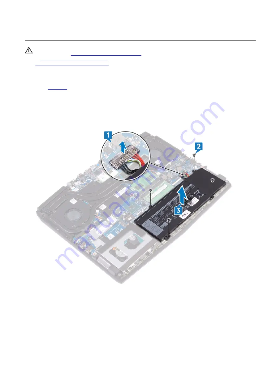
Removing the battery (half-length)
WARNING: Before working inside your computer, read the safety information that shipped with your computer and
follow the steps in
Before working inside your computer
. After working inside your computer, follow the instructions
After working inside your computer
. For more safety best practices, see the Regulatory Compliance home page at
www.dell.com/regulatory_compliance
Prerequisites
Remove the
Procedure
1
Using the pull tab, disconnect the battery cable from the system board (applicable only if not disconnected earlier).
2 Remove the four screws (M2x5) that secure the battery to the palm-rest assembly.
3 Lift the battery off the palm-rest assembly.
22
Содержание Alienware m15
Страница 17: ...5 Rotate the base cover from front to back and remove the base cover off the palm rest assembly 17 ...
Страница 21: ...5 Replace the two screws M2 5x10 in the back that secure the base cover to the palm rest assembly 21 ...
Страница 30: ...Post requisites Replace the base cover 30 ...
Страница 32: ...3 Remove the memory modules from the memory module slot 32 ...
Страница 35: ...6 Lift the heat sink assembly off the system board 7 Remove the fans 35 ...
Страница 37: ...7 Connect the right fan cable to the system board Post requisites Replace the base cover 37 ...
Страница 39: ...5 Lift the fans off the heat sink 39 ...
Страница 43: ...5 Disconnect the antenna cables from the wireless card 43 ...
Страница 54: ...4 Lift the I O board off the palm rest assembly 54 ...
Страница 56: ...4 Adhere the tape that secures the I O board cable to the I O board Post requisites Replace the base cover 56 ...
Страница 67: ...5 Remove the two screws M2 5x2 5 that secures the hinges to the palm rest assembly 67 ...
Страница 68: ...6 Rotate the display assembly inward and lift up and away from the palm rest assembly 68 ...
Страница 75: ...13 Lift the system board off the palm rest assembly 75 ...
Страница 85: ...4 Peel the left black Mylar along with the blue Mylar from the clear release paper 85 ...
Страница 86: ...5 Using the alignment holes adhere the keyboard Mylar on the left side of the keyboard bracket 86 ...
Страница 87: ...6 Peel the right black Mylar along with the blue Mylar from the clear release paper 87 ...
Страница 88: ...7 Using the alignment holes adhere the keyboard Mylar on the right side of the keyboard bracket 88 ...
Страница 89: ...8 Peel the blue Mylar from both the sides 89 ...
Страница 92: ...92 ...


