


Replacing the computer base
WARNING: Before working inside your computer, read the safety information that shipped with your computer and
follow the steps in
Before working inside your computer
. After working inside your computer, follow the instructions
After working inside your computer
. For more safety best practices, see the Regulatory Compliance home page at
www.dell.com/regulatory_compliance
Procedure
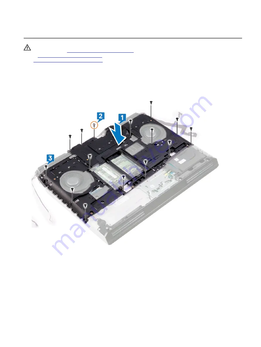
1
Align the screw holes on the computer base with the screw holes on the palm-rest assembly.
2 Replace the screw (M2.5x12) that secures the computer base to the palm-rest assembly.
3 Replace the 14 screws (M2.5x8) that secure the computer base to the palm-rest assembly.
4 Adhere the display cable and camera cable to the computer base.
5 Connect the camera cable to the system board.
6 Connect the display cable to the system board.
7 Align the screw hole on the display-cable bracket with the screw hole on the system board.
8 Replace the screw (M2x3) that secures the display-cable bracket to the system board.
9 Adhere the tobii cable to the computer base.
10 Route the antennas cable through the routing guides on the computer base.
11 Connect the tobii cable to the system board.
12 Route the hard-drive cable through routing guides on the computer base.
60
Содержание Alienware Area-51m
Страница 18: ...3 Tighten the six captive screws that secure the base cover to the computer base 18 ...
Страница 20: ...3 Lift the battery off the palm rest assembly 20 ...
Страница 23: ...3 Remove the memory module from the memory module slot 23 ...
Страница 26: ...5 Disconnect the antenna cables from the wireless card 26 ...
Страница 28: ...Post requisites Replace the base cover 28 ...
Страница 38: ...Post requisites Replace the base cover 38 ...
Страница 45: ...4 Replace the base cover 45 ...
Страница 49: ...6 Lift the touchpad off the palm rest assembly 49 ...
Страница 54: ...12 Lift the display assembly off the palm rest assembly 54 ...
Страница 59: ...13 Lift the computer base off the palm rest assembly 59 ...
Страница 63: ...4 Lift the heat sink assembly off the system board 63 ...
Страница 68: ...7 Replace the base cover 68 ...
Страница 70: ...4 Lift the processor straight up to remove it from the system board 70 ...
Страница 73: ...5 Lift the graphics card off the system board 73 ...
Страница 75: ...6 Replace the battery 7 Replace the base cover 75 ...
Страница 78: ...11 Remove the left power adapter port 78 ...
Страница 79: ...12 After performing all the above steps you are left with the system board 79 ...
Страница 84: ...84 ...
Страница 86: ...10 Replace the battery 11 Replace the base cover 86 ...
Страница 89: ...8 Lift the keyboard from bottom and slide out of the clips at top 89 ...
Страница 93: ...93 ...
Страница 95: ...11 Replace the battery 12 Replace the base cover 95 ...
Страница 97: ...97 ...