Service Manual
System Outline
4-8
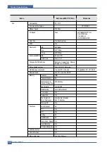
ASIC
Items
Specification
Remark
Process
0.13um (STDH150)
Package
- 496 PBGA (total pad number:597ea)
- Function pin: about 367pins
- PWR & GND pin: 130pins ( (130/496)
100 = 26.2 %)
- PWR & GND pad: 204ea ((204/597) 100 = 34.17%)
Voltage
- Core Voltage: 1.2V
- I/O Pad Voltage: 3.3V ?RTC Voltage : 3V
CPU Core
ARM 920T (I-Cache: 16KB, D-Cache-16KB)
Operating Freq.
- CPU Core: over 300MHz
- Target System Bus: 100MHz
SDRAMC
- 32 Bits Only, 100MHz
- 5 Banks (Up to 128MB per Bank)
- Feed-back clock(for SDRAM read) is appended
ROMC
4 Banks (Up to 16MB per Bank)
IOC
6 Banks (Up to 16MB per Bank)
DMAC
6 Channels
(if not use CIP4e, 4ch is available for external DMA. if CIP4E
used (a4 DMA channel use), 2ch available for external DMA)
HPVC
- Dual / Single Beam
- LVDS Pad (VDO, HSYNC)
- Support A4 600dpi, multi-pass color.
PVC
- Dual / Single Beam
- LVDS Pad (VDO, HSYNC)
- Support A3 1200dpi, multi-pass color.
UART
5 Channels (Channel0 supports DMA/interrupt Operation )
INTERRUPT
6 External Interrupts, 26 Internal Interrupts
TIMER
6 System Timers
CIP4e
-300/400/600/1200dpi CIS/CCD image sensor interface
-Color/Mono grey image, Binary image scan support
-600dpi Color/Mono Copy support
-Image processing for High-End MFP, Digital Copier,
-MH/MR/MMR CODEC function for fax
- Scan image :(max) A4 1200dpi pixel processing,
-Copy image :(max) A4 600dpi pixel processing
NAND Flash
- 8/16 Bits, H/W ECC Generation
Controller
- Auto Boot Mode (using internal SRAM, 4KB)
MAC
- 10M/100Mbps
- Full IEEE 802.3 compatibility
PPI
IEEE1284 compliant parallel port interface
GEU
Graphic Execution Unit
*PWR & GND pin :
114ea*Dedicated PWR
& GND pin(ring, rtc,
lvds, pll): 16ea
Содержание 1815 Mono Laser
Страница 1: ...Dell 1815dn Service Manual 27 Mar 2006 ...
Страница 28: ...Service Manual System Outline 4 10 ...
Страница 126: ...Exploded View Parts List Service Manual 8 3 8 2 Cover Ass y 0 1 2 2 3 2 1 2 2 3 4 5 5 1 5 2 6 ...
Страница 127: ...Service Manual Exploded View Parts List 8 4 8 3 Middle Cover Ass y 0 1 2 3 4 5 6 6 ...
Страница 128: ...Exploded View Parts List Service Manual 8 5 8 4 Front Cover Ass y 0 1 2 3 4 5 10 10 8 9 7 6 11 ...
Страница 129: ...Service Manual Exploded View Parts List 8 6 8 5 Rear Cover Ass y 0 1 2 3 7 4 5 6 8 ...
Страница 131: ...Service Manual Exploded View Parts List 8 8 8 7 Fuser Drive Ass y 0 1 2 3 5 5 6 7 8 9 4 ...
Страница 132: ...Exploded View Parts List Service Manual 8 9 8 8 Main Drive Ass y 0 2 4 1 3 5 6 8 7 6 7 3 ...
Страница 135: ...Service Manual Exploded View Parts List 8 12 8 11 Cover Platen Ass y 0 1 1 1 1 2 1 3 1 4 1 5 2 3 4 4 5 6 7 7 5 8 9 ...
Страница 136: ...Exploded View Parts List Service Manual 8 13 8 12 OPE Unit 0 1 2 3 4 5 6 7 8 ...
Страница 149: ...Block Diagram Service Manual 9 1 9 9 9 Block Diagram ...
Страница 150: ...Connection Diagram Service Manual 10 1 10 10 10 Connection Diagram ...

