


MX7K-IOM-A2(conf-if-vl-2712)# exit
MX7K-IOM-A2#
NOTE:
Follow the same procedure to create other VLANs.
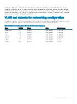
When you verify the running configuration of the switches, you should see a resulting configuration similar to the data below. VLAN IDs and
descriptions vary depending on the environment.
interface vlan1611
description Management
no shutdown
mtu 9216
!
interface vlan1612
description VMotion
no shutdown
mtu 9216
!
interface vlan1613
description VSAN
no shutdown
mtu 9216
!
interface vlan1614
description "VXLAN NSX VTEP"
no shutdown
mtu 9216
!
interface vlan2711
description "Uplink1"
no shutdown
mtu 9216
!
interface vlan2712
description "Uplink2"
no shutdown
mtu 9216
!
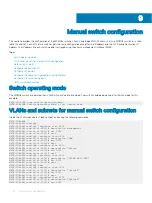
Uplink and VLTi ports
VLT synchronizes Layer 2 table information between the switches and enables them to display as a single logical unit from outside the VLT
domain. The VLT interconnect (VLTi) between the two Dell EMC MX5108n switches is a port group that is generated by configuring a VLT
domain and specifying the discovery interfaces. When using the MX9116n FSEs and MX7116n FEMs, the uplink ports will be ports 40 and
42.
Before you start, verify that the mode for ports 1/1/9 and 1/1/10 on the back of the MX5108n switches are set to 40 G.
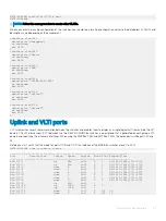
MX7K-IOM-A2# show interface status
-------------------------------------------------------------------------------
Port Description Status Speed Duplex Mode Vlan Tagged-Vlans
-------------------------------------------------------------------------------
Eth 1/1/1 up 25G full T 1 96,1611-1614,2711-2712
Eth 1/1/2 up 25G full T 1 96,1611-1614,2711-2712
Eth 1/1/3 down 0 full T 1 96,1611-1614,2711-2712
Eth 1/1/4 down 0 full T 1 96,1611-1614,2711-2712
Eth 1/1/5 down 0 full T 1 96,1611-1614,2711-2712
Eth 1/1/6 down 0 full T 1 96,1611-1614,2711-2712
Eth 1/1/7 down 0 full T 1 96,1611-1614,2711-2712
Eth 1/1/8 down 0 full T 1 96,1611-1614,2711-2712
Eth 1/1/9 up 40G full -
Eth 1/1/10 up 100G full A 1 -
Eth 1/1/11 up 100G full -
Eth 1/1/12 down 0 full T 96 15
Eth 1/1/13 down 0 full T 96 15
Manual switch configuration
47
Содержание PowerEdge MX7000
Страница 1: ...Dell EMC VMware Cloud Foundation for PowerEdge MX7000 Deployment Guide ...
Страница 8: ...Figure 1 Cloud Foundation deployment workflow 8 Overview ...
Страница 27: ...Figure 19 Dual PowerEdge MX7000 enclosure configuration Physical layout 27 ...
Страница 29: ...Figure 20 MX9002m Management module cabling Physical layout 29 ...
Страница 30: ...Figure 21 Connectivity between FSE modules and FEM modules 30 Physical layout ...
Страница 31: ...Figure 22 Uplinks to customer network environment Physical layout 31 ...
Страница 42: ...Figure 25 MX9002m Management Module cabling 42 Networking requirements ...
Страница 43: ...Figure 26 Connectivity between FSE modules and FEM modules Networking requirements 43 ...
Страница 44: ...Figure 27 Uplinks to customer network environment 44 Networking requirements ...


