
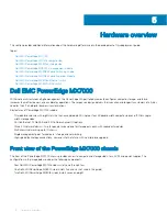


Figure 3. PowerEdge MX7000 chassis—front view
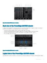
Back view of the PowerEdge MX7000 chassis
The back of the PowerEdge MX7000 chassis provides access to network and storage fabrics, management modules, fans, and power
connections. The configuration in the image below includes the following components:
•
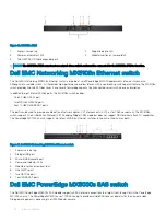
Two Dell EMC Networking MX5108n Ethernet switches installed in fabric slots A1 and A2
•
Two Dell EMC PowerEdge MX9002m management modules that are installed in management slots MM1 and MM2
•
Two Dell EMC PowerEdge MX5000s SAS fabric switch modules that are installed in fabric slots C1 and C2
•
Empty or available fabric slots B1 and B2
Figure 4. PowerEdge MX7000 chassis—rear view
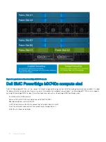
Logical view of the PowerEdge MX7000 chassis
PowerEdge MX7000 supports three fabrics—two for general use and one for storage only. All three fabrics support redundant modules.
Hardware overview
15
Содержание PowerEdge MX7000
Страница 1: ...Dell EMC VMware Cloud Foundation for PowerEdge MX7000 Deployment Guide ...
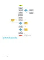
Страница 8: ...Figure 1 Cloud Foundation deployment workflow 8 Overview ...
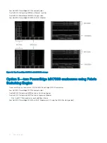
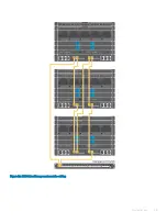
Страница 27: ...Figure 19 Dual PowerEdge MX7000 enclosure configuration Physical layout 27 ...
Страница 29: ...Figure 20 MX9002m Management module cabling Physical layout 29 ...
Страница 30: ...Figure 21 Connectivity between FSE modules and FEM modules 30 Physical layout ...
Страница 31: ...Figure 22 Uplinks to customer network environment Physical layout 31 ...
Страница 42: ...Figure 25 MX9002m Management Module cabling 42 Networking requirements ...
Страница 43: ...Figure 26 Connectivity between FSE modules and FEM modules Networking requirements 43 ...
Страница 44: ...Figure 27 Uplinks to customer network environment 44 Networking requirements ...


