background image

Removing the wireless card

NOTE: 

Before working inside your computer, read the safety information that shipped with your computer and follow 

the steps in 

Before working inside your computer

. After working inside your computer, follow the instructions in 

After 

working inside your computer

. For more safety best practices, see the Regulatory Compliance home page at 

www.dell.com/regulatory_compliance

.

Procedure

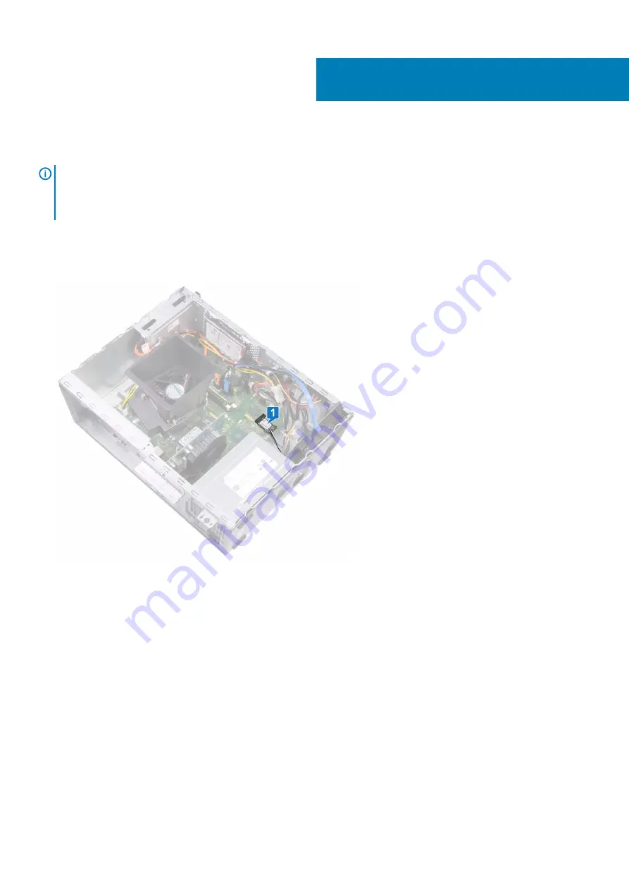
1. Locate the wireless card on the system board.

2. Remove the screw (M2x3.5) that secures the wireless card to the system board.
3. Lift the wireless-card bracket off the wireless card.
4. Disconnect the antenna cables from the wireless card.
5. Slide and remove the wireless card from the wireless-card slot on the system board.

16

26

Removing the wireless card

Содержание Inspiron 3671

Страница 1: ...Inspiron 3671 Service Manual Regulatory Model D19M Regulatory Type D19M005 ...

Страница 2: ...amage to hardware or loss of data and tells you how to avoid the problem WARNING A WARNING indicates a potential for property damage personal injury or death 2019 Dell Inc or its subsidiaries All rights reserved Dell EMC and other trademarks are trademarks of Dell Inc or its subsidiaries Other trademarks may be trademarks of their respective owners 2019 11 Rev A01 ...

Страница 3: ... view of your computer 13 5 System board components 14 6 Removing the computer cover 15 Procedure 15 7 Replacing the computer cover 16 Procedure 16 8 Removing the front bezel 17 Procedure 17 Prerequisites 18 9 Replacing the front bezel 19 Procedure 19 Post requisites 19 10 Removing the memory module 20 Prerequisites 20 Procedure 20 11 Replacing the memory module 21 Procedure 21 Post requisites 21 ...

Страница 4: ...cedure 28 Post requisites 28 18 Removing the power supply unit 29 Prerequisites 29 Procedure 29 19 Replacing the power supply unit 30 Procedure 30 Post requisites 30 20 Removing the 3 5 inch hard drive 31 Prerequisites 31 Procedure 31 21 Replacing the 3 5 inch hard drive 32 Procedure 32 Post requisites 32 22 Removing the 2 5 inch hard drive 33 Prerequisites 33 Procedure 33 23 Replacing the 2 5 inc...

Страница 5: ...nd heat sink assembly 44 Procedure 44 Post requisites 45 30 Removing the processor 46 Prerequisites 46 Procedure 46 31 Replacing the processor 47 Procedure 47 Post requisites 47 32 Removing the antenna modules 48 Prerequisites 48 Procedure 48 33 Replacing the antenna modules 49 Procedure 49 Post requisites 49 34 Removing the system board 50 Prerequisites 50 Procedure 50 35 Replacing the system boa...

Страница 6: ...edure 68 Post requisites 68 37 Troubleshooting 69 Enhanced Pre Boot System Assessment ePSA diagnostics 69 Running the ePSA diagnostics 69 Diagnostics 69 Recovering the operating system 70 Flashing BIOS USB key 70 Flashing the BIOS 70 Enabling Intel Optane memory 71 Disabling Intel Optane memory 71 WiFi power cycle 71 Flea power release 71 38 Getting help and contacting Dell 73 6 Contents ...

Страница 7: ...grounding strap or by periodically touching an unpainted metal surface such as the metal at the back of the computer While you work periodically touch an unpainted metal surface to dissipate static electricity which could harm internal components CAUTION When you disconnect a cable pull on its connector or on its pull tab not on the cable itself Some cables have connectors with locking tabs or thu...

Страница 8: ... Field Service kit is the most commonly used service kit Each Field Service kit includes three main components anti static mat wrist strap and bonding wire Components of an ESD field service kit The components of an ESD field service kit are Anti Static Mat The anti static mat is dissipative and parts can be placed on it during service procedures When using an anti static mat your wrist strap shou...

Страница 9: ...eep sensitive parts separate from all insulator parts while performing service and that they use anti static bags for transporting sensitive components Transporting sensitive components When transporting ESD sensitive components such as replacement parts or parts to be returned to Dell it is critical to place these parts in anti static bags for safe transport Lifting equipment Adhere to the follow...

Страница 10: ...Recommended tools The procedures in this document may require the following tools Phillips screwdriver 1 Flat head screwdriver Plastic scribe 2 10 Recommended tools ...

Страница 11: ...color may vary with the configuration ordered Table 1 Screw list Component Secured to Screw type Quantity Screw image Computer cover Chassis 6 32x6 35 2 Solid state drive Intel Optane memory System board M2x3 5 1 Card retention bracket Chassis 6 32x6 35 1 Wireless card System board M2x3 5 1 Power supply unit Chassis 6 32x6 35 4 3 5 inch hard drive Chassis 6 32x3 6 4 2 5 inch hard drive s NOTE Depe...

Страница 12: ...Component Secured to Screw type Quantity Screw image System board Chassis 6 32x4 8 standoff 1 12 Screw list ...

Страница 13: ... heat sink assembly 2 solid state drive Intel Optane memory 3 graphics card 4 power supply unit 5 wireless card 6 3 5 inch hard drive 7 2 5 inch hard drive 8 system board 9 memory module s 10 coin cell battery 11 2 5 inch hard drive 12 optical disk drive 4 Inside view of your computer 13 ...

Страница 14: ... SATA 3 7 SATA 0 cable connector SATA 0 8 hard drive power cable connector SATA PWR 9 power supply unit cable connector ATX PWR 10 wireless card slot 11 service mode jumper 12 CMOS clear jumper 13 password clear jumper 14 M 2 PCIe connector 15 PCI Express x16 slot 16 PCI Express X1 slot 17 PCI Express X1 slot 18 processor power cable connector ATX CPU 19 processor socket 5 14 System board componen...

Страница 15: ...llow the instructions in After working inside your computer For more safety best practices see the Regulatory Compliance home page at www dell com regulatory_compliance Procedure 1 Place the computer on its side 2 Remove the two screws 6 32x6 35 that secure the computer cover to the chassis 3 Slide the computer cover towards the back of the computer and lift the computer cover off the chassis 6 Re...

Страница 16: ...ter working inside your computer For more safety best practices see the Regulatory Compliance home page at www dell com regulatory_compliance Procedure 1 Align the tabs on the computer cover with the slots on the chassis and slide it towards the front of the computer until it snaps into position 2 Replace the two screws 6 32x6 35 that secure the computer cover to the chassis 3 Place the computer i...

Страница 17: ...structions in After working inside your computer For more safety best practices see the Regulatory Compliance home page at www dell com regulatory_compliance Procedure 1 Place the computer in an upright position 2 Pry and release the tabs on the front bezel away from the chassis 3 Rotate and pull the front bezel away from the computer to release the tabs on the front bezel from the slots on the ch...

Страница 18: ...Prerequisites Remove the computer cover 18 Removing the front bezel ...

Страница 19: ...de your computer For more safety best practices see the Regulatory Compliance home page at www dell com regulatory_compliance Procedure 1 Align the tabs on the front bezel with the slots on the chassis and then rotate the front bezel towards the chassis until it snaps into place NOTE Ensure that the front bezel slot is aligned correctly with the optical drive 2 Place the computer on its side Post ...

Страница 20: ... www dell com regulatory_compliance Prerequisites Remove the computer cover Procedure NOTE Depending on the configuration ordered your computer may have up to two memory modules installed on the system board 1 Using the fingertips spread apart the securing clip at each end of the memory module slot until the memory module pops up 2 Lift the memory module out of the memory module slot NOTE If the m...

Страница 21: ...For more safety best practices see the Regulatory Compliance home page at www dell com regulatory_compliance Procedure 1 Align the notch on the memory module with the tab on the memory module slot NOTE Ensure that the securing clips are extended away from the memory module slot 2 Insert the memory module into the memory module slot and then press the memory module down until the securing clips loc...

Страница 22: ...er working inside your computer follow the instructions in After working inside your computer For more safety best practices see the Regulatory Compliance home page at www dell com regulatory_compliance Prerequisites Remove the computer cover Procedure 1 Locate the solid state drive or Intel Optane memory on the system board 2 Remove the screw M2x3 5 that secures the solid state drive or Intel Opt...

Страница 23: ...ng inside your computer For more safety best practices see the Regulatory Compliance home page at www dell com regulatory_compliance CAUTION Solid state drives are fragile Exercise care when handling the solid state drive Procedure 1 Align the notch on the solid state drive or Intel Optane memory with the tab on the M 2 card slot 2 Slide the solid state drive or Intel Optane memory into the M 2 ca...

Страница 24: ...Regulatory Compliance home page at www dell com regulatory_compliance CAUTION Removing the coin cell battery resets the BIOS setup program s settings to default It is recommended that you note the BIOS setup program s settings before removing the coin cell battery Procedure 1 Press on the edge of the coin cell battery to release it from the battery socket on the system board 2 Lift the coin cell b...

Страница 25: ...ing inside your computer follow the instructions in After working inside your computer For more safety best practices see the Regulatory Compliance home page at www dell com regulatory_compliance Procedure Insert the coin cell battery into the battery socket with the positive side facing up and snap the battery into place Post requisites Replace the computer cover 15 Replacing the coin cell batter...

Страница 26: ...omputer For more safety best practices see the Regulatory Compliance home page at www dell com regulatory_compliance Procedure 1 Locate the wireless card on the system board 2 Remove the screw M2x3 5 that secures the wireless card to the system board 3 Lift the wireless card bracket off the wireless card 4 Disconnect the antenna cables from the wireless card 5 Slide and remove the wireless card fr...

Страница 27: ...Prerequisites Remove the computer cover Removing the wireless card 27 ...

Страница 28: ...ess card bracket on the wireless card and align the screw hole on the bracket with the screw hole on the wireless card The following table provides the antenna cable color scheme for the wireless card supported by your computer Table 2 Antenna cable color scheme Connectors on the wireless card Antenna cable color Main white triangle White Auxiliary black triangle Black 3 Align the notch on the wir...

Страница 29: ... www dell com regulatory_compliance Prerequisites Remove the computer cover Procedure 1 Press the securing clip and disconnect the power supply unit cable P1 from the system board ATX SYS 2 Press the securing clip and disconnect the power supply unit cable P2 from the processor power cable ATX CPU 3 Remove the power supply unit cable P1 from the routing guide on the chassis 4 Remove the four screw...

Страница 30: ... dell com regulatory_compliance Procedure 1 Place the power supply unit on the chassis aligning the screw holes on the power supply unit to the screw holes on the chassis 2 Replace the four screws 6 32x6 35 that secure the power supply unit to the chassis 3 Route the power supply unit cable ATX SYS through the routing guide on the chassis 4 Connect the power supply unit cable P1 to the system boar...

Страница 31: ...s in After working inside your computer For more safety best practices see the Regulatory Compliance home page at www dell com regulatory_compliance Prerequisites 1 Remove the computer cover 2 Remove the front bezel Procedure 1 Disconnect the hard drive data cable and power cable from the hard drive 2 Remove the four screws 6 32x3 6 that secure the hard drive to the chassis 3 Lift the hard drive o...

Страница 32: ...For more safety best practices see the Regulatory Compliance home page at www dell com regulatory_compliance Procedure 1 Place the hard drive on the chassis and align the screw holes on the hard drive with the screw holes on the chassis 2 Replace the four screws 6 32x3 6 that secure the hard drive to the chassis 3 Connect the hard drive data cable and power cable to the hard drive Post requisites ...

Страница 33: ... cover 2 Remove the front bezel Procedure NOTE Depending on the configuration ordered there may be up to two 2 5 inch hard drives installed in your computer The following procedure enables you to remove the 2 5 inch hard drive s in either or both locations 1 Disconnect the hard drive data cable and power cable from the hard drive 2 Remove the two screws M3x3 5 that secure the hard drive to the cha...

Страница 34: ...34 Removing the 2 5 inch hard drive ...

Страница 35: ...Depending on the configuration ordered there may be up to two 2 5 inch hard drives installed in your computer The following procedure lists the steps to remove the 2 5 inch hard drive s in either or both locations 1 Align and place the slots on the hard drive with the posts on the chassis then hold the hard drive in place NOTE Ensure that the hard drive is seated correctly with the posts on the ch...

Страница 36: ...Post requisites 1 Replace the front bezel 2 Replace the computer cover 36 Replacing the 2 5 inch hard drive ...

Страница 37: ...ct the optical drive data cable and power cable from the optical drive assembly 2 Remove the two screws M2x2 that secure the optical drive assembly to the chassis 3 Slide and remove the optical drive assembly from its slot on the chassis 4 Insert a pin into the optical drive emergency eject pinhole to release the optical drive tray 5 Gently pull to open the optical drive tray from the optical driv...

Страница 38: ...Prerequisites Remove the computer cover 38 Removing the optical drive ...

Страница 39: ... Compliance home page at www dell com regulatory_compliance Procedure 1 Align and replace the optical drive bezel to the optical drive tray 2 Slide the optical drive assembly into its slot on the chassis and align the screw holes on the optical drive assembly to the screw holes on the chassis 3 Replace the screws M2x2 that secures the optical drive assembly to the chassis 4 Connect the optical dri...

Страница 40: ...st practices see the Regulatory Compliance home page at www dell com regulatory_compliance Prerequisites Remove the computer cover Procedure 1 Remove the screw 6 32x6 35 that secures the card retention bracket to the chassis 2 Rotate the card retention bracket away from the chassis to access the expansion cards 3 Push and hold the securing tab on the graphics card slot 4 Hold firmly on the edge of...

Страница 41: ...pushed away from the graphics card slot 2 Align the notch on the graphics card with the tab on the graphics card slot and then press down firmly until the graphics card snaps into place NOTE The securing tab will move to a closed position when the graphics card is replaced correctly Remove the graphics card and repeat the procedure if the securing tab does not close 3 Rotate the card retention bra...

Страница 42: ... maximum cooling of the processor do not touch the heat transfer areas on the heat sink The oils in your skin can reduce the heat transfer capability of the thermal grease Prerequisites Remove the computer cover Procedure 1 Pry and release the tabs that secure the fan shroud to the processor fan and heat sink assembly 2 Lift the fan shroud off the processor fan and heat sink assembly 3 Disconnect ...

Страница 43: ...Removing the processor fan and heat sink assembly 43 ...

Страница 44: ...y with the screw holes on the system board NOTE As shown in the image ensure that the processor fan cable faces the front of the computer before tightening the captive screws 2 In sequential order as indicated on the system board tighten the four captive screws that secure the processor fan and heat sink assembly to the system board 3 Connect the processor fan cable to the system board FAN CPU 4 P...

Страница 45: ...Post requisites Replace the computer cover Replacing the processor fan and heat sink assembly 45 ...

Страница 46: ...For more safety best practices see the Regulatory Compliance home page at www dell com regulatory_compliance Prerequisites 1 Remove the computer cover 2 Remove the processor fan and heat sink assembly Procedure 1 Press the release lever down and then push it away from the processor to release it from the securing bracket 2 Pull the release lever up completely to unlock the processor 3 Gently lift ...

Страница 47: ... position Then align the notches on the processor with the tabs on the processor socket and place the processor in the processor socket CAUTION The pin 1 corner of the processor is marked with a triangle that must align with the triangle marking on the pin 1 corner on the processor socket to ensure that the processor is properly seated When the processor is properly seated all four corners are ali...

Страница 48: ...computer For more safety best practices see the Regulatory Compliance home page at www dell com regulatory_compliance Prerequisites 1 Remove the computer cover 2 Remove the front bezel 3 Follow the procedure from step 1 to step 4 in Removing the wireless card Procedure 1 Using a plastic scribe pry and peel the antenna modules 2 from the locations on the chassis 2 Pull and route the antenna cables ...

Страница 49: ...ctices see the Regulatory Compliance home page at www dell com regulatory_compliance Procedure 1 Using the alignment posts adhere the antenna modules 2 to the chassis NOTE Ensure the antenna modules ANT W and ANT B are replaced in the correct locations on the chassis 2 Slide and route the antenna cables through the antenna cable slot on the chassis Post requisites 1 Follow steps 1 2 and 4 in Repla...

Страница 50: ...emove the memory module 4 Remove the solid state drive Intel Optane memory 5 Remove the graphics card 6 Remove the wireless card 7 Remove the processor fan and heat sink assembly 8 Remove the processor Procedure NOTE Note the routing of all cables as you remove them so that you can reroute them correctly after you replace the system board For information on system board connectors see System board...

Страница 51: ...e chassis 10 Remove the screw 6 32x4 8 standoff that secures the system board to the chassis 11 Remove the screw 6 32x6 35 that secures the front I O bracket to the chassis 12 Remove the front I O bracket from the front I O slot on the chassis Removing the system board 51 ...

Страница 52: ...3 Lift the system board and slide it toward the front I O slot releasing the back I O ports from the back I O bracket 14 Lift the system board and remove it from the chassis 52 Removing the system board ...

Страница 53: ...Removing the system board 53 ...

Страница 54: ...ystem board NOTE Replacing the system board removes any changes you have made to the BIOS using the BIOS setup program You must make the appropriate changes again after you replace the system board Procedure NOTE To ensure that cables are connected to the correct system board connectors see System board components NOTE Depending on the configuration ordered your computer may have up to two 2 5 inc...

Страница 55: ...32x4 8 standoff that secures the system board to the chassis 5 Slide the front I O bracket into the front I O slot aligning the screw hole on the front I O board to the screw hole on the chassis 6 Replace the screw 6 32x6 35 that secures the front I O bracket to the chassis Replacing the system board 55 ...

Страница 56: ...ATA PWR 10 Connect the hard drive data cable to the system board SATA 3 11 Connect the hard drive cable to the system board SATA 0 12 Connect the hard drive data cable to the system board SATA 1 13 Connect the optical drive data cable to the system board SATA 2 14 Connect the processor power cable to the system board ATX SYS Post requisites 1 Replace the processor 56 Replacing the system board ...

Страница 57: ...t sink assembly 3 Replace the wireless card 4 Replace the graphics card 5 Replace the solid state drive Intel Optane memory 6 Replace the memory module 7 Replace the front bezel 8 Replace the computer cover Replacing the system board 57 ...

Страница 58: ...m Setup options changes that you make are recorded but do not take effect until you restart the system Keys Navigation Up arrow Moves to the previous field Down arrow Moves to the next field Enter Selects a value in the selected field if applicable or follow the link in the field Spacebar Expands or collapses a drop down list if applicable Tab Moves to the next focus area Esc Moves to the previous...

Страница 59: ...s the total computer memory available Memory Speed Displays the memory speed Memory Channel Mode Displays single or dual channel mode Memory Technology Displays the technology used for the memory DIMM 1 Size Displays the DIMM 1 memory size DIMM 2 Size Displays the DIMM 2 memory size PCI Information Slot1 Displays the PCI information of Slot1 Slot2 Displays the PCI information of Slot2 Slot3 Displa...

Страница 60: ...The options are Windows Boot Manager Onboard NIC IPV4 Oboard NIC IPV6 By default all the check boxes are selected You can clear the check boxes or change the boot order Boot List Option Displays the available boot options Allows you to change the boot list option Legacy External Devices UEFI default You can also add or delete a boot option Advanced Boot Options Enable or disable legacy boot option...

Страница 61: ...r OS If USB port is disabled the OS cannot detect any device attached to this port Enable USB Boot Support Enable Front USB Ports Enable Rear USB Ports By default all the check boxes are selected NOTE USB keyboard and mouse always work in the BIOS setup irrespective of these settings Front USB Configuration Enable or disable the front USB ports Front Port 1 Front Port 2 By default all the check bo...

Страница 62: ...HDD 0 Password Set change or delete the internal hard disk drive password NOTE Successful password changes take effect immediately Internal HDD 0Password Set change or delete the internal hard disk drive password NOTE Successful password changes take effect immediately Internal HDD 1 Password Set change or delete the internal hard disk drive password NOTE Successful password changes take effect im...

Страница 63: ...s not selected Secure Boot Mode Set the Secure Boot Mode to allow evaluation or enforcement of UEFI driver signatures Deployed Mode default Audit Mode Expert Key Management Allows you to manipulate the security key databases only if the computer is in Custom Mode By default Enable Custom Mode is selected If Enable Custom Mode is selected the options are PK default KEK db dbx After selecting an opt...

Страница 64: ...processor sleep states By default C states is selected Intel TurboBoost Enable or disable Intel TurboBoost mode of the processor By default Enable Intel TurboBoost is selected Table 10 System setup options Power Management menu Power Management AC Recovery Enable or disable the automatic power on when an AC adapter is connected Power Off default Power On Last Power State Enable Intel Speed Shift T...

Страница 65: ... default Enable Keyboard Error Detection is selected Fastboot Enable to set the speed of the boot process by bypassing some of the compatibility steps Minimal Thorough default Auto Extend BIOS POST Time Set the BIOS POST time for an additional pre boot delay 0 seconds default 5 seconds 10 seconds Full Screen Logo Display the full screen logo if your image matches the screen resolution By default E...

Страница 66: ... the user primary hard drive By default BIOS Recovery from Hard Drive is selected First Power On Date Set the date on which the computer is switched on for ownership record By default Set Ownership Date is not selected Table 15 System setup options System Logs menu System Logs BIOS Events Display BIOS events Table 16 System setup options Advanced configurations menu System Logs ASPM Set the Active...

Страница 67: ...tory_compliance Prerequisites Remove the computer cover Procedure 1 Locate the password jumper PSWD on the system board NOTE For more information on the location of the jumper see System board components 2 Remove the jumper plug from the password jumper pins 3 Wait for 5 seconds and then replace the jumper plug in its original location Post requisites Replace the computer cover Clearing CMOS Setti...

Страница 68: ...ocedure 1 Locate the CMOS jumper CMCL R2 on the system board NOTE For more information on the location of the jumper see System board components 2 Remove the jumper plug from the password jumper pins PSWD and connect it to the CMOS jumper pins 3 Wait for 5 seconds and then replace the jumper plug to its original location Post requisites Replace the computer cover 68 System setup ...

Страница 69: ...boot menu screen select the Diagnostics option 4 Click the arrow at the bottom left corner Diagnostics front page is displayed 5 Click the arrow in the lower right corner to go to the page listing The items detected are listed 6 To run a diagnostic test on a specific device press Esc and click Yes to stop the diagnostic test 7 Select the device from the left pane and click Run Tests 8 If there are...

Страница 70: ...nformation about the Dell SupportAssist OS Recovery see Dell SupportAssist OS Recovery User s Guide at www dell com support Flashing BIOS USB key 1 Follow the procedure from step 1 to step 7 in Flashing the BIOS to download the latest BIOS setup program file 2 Create a bootable USB drive For more information see the knowledge base article SLN143196 at www dell com support 3 Copy the BIOS setup pro...

Страница 71: ... from the computer 1 On the taskbar click the search box and then type Intel Rapid Storage Technology 2 Click Intel Rapid Storage Technology The Intel Rapid Storage Technology window is displayed 3 On the Intel Optane memory tab click Disable to disable the Intel Optane memory NOTE For computers in which Intel Optane memory acts as a primary storage do not disable the Intel Optane memory The Disab...

Страница 72: ...3 Press and hold down the power button for 15 seconds to drain the flea power 4 Connect the power cable 5 Turn on your computer 72 Troubleshooting ...

Страница 73: ... the related articles Learn and know the following information about your product Product specifications Operating system Setting up and using your product Data backup Troubleshooting and diagnostics Factory and system restore BIOS information See Me and My Dell at www dell com support manuals To locate the Me and My Dell relevant to your product identify your product through one of the following ...

Отзывы: