


Replacing the system board
NOTE:
Before working inside your computer, read the safety information that shipped with your computer and follow
the steps in
Before working inside your computer
. After working inside your computer, follow the instructions in
. For more safety best practices, see the Regulatory Compliance home page at
www.dell.com/regulatory_compliance
NOTE:
Your computer’s Service Tag is stored in the system board. You must enter the Service Tag in the BIOS setup
program after you replace the system board.
NOTE:
Replacing the system board removes any changes you have made to the BIOS using the BIOS setup program. You
must make the appropriate changes again after you replace the system board.
Topics:
•
•
Procedure
1. Connect the power-adapter port cable to the system board.
CAUTION:
To avoid damaging the system board, ensure that no cables are placed under it.
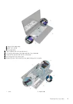
2. Slide the I/O-board cable into its connector on the system board and press down the latch to secure the cable.
3. Connect the power-adapter port cable to the system board
4. Turn the system board over.
5. Slide the ports on the system board into the slots on the palm-rest assembly and place the system board on the palm-rest assembly.
6. Align the screw hole on the system board with the screw hole on the palm-rest assembly.
7. Replace the screw that secures the system board to the palm-rest assembly.
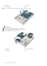
8. Adhere the tape to the antenna cables.
9. Connect the speaker cable to the system board.
10. Slide the display cable into its connector on the system board and press down the latch to secure the cable.
11. Turn the computer over and open the display as far as possible.
12. Slide the touch-pad cable and the power-button board cable into their connectors on the system board and press down the latches to
secure the cables.
Post-requisites
1. Replace the
2. Replace the
3. Replace the
4. Replace the
.
5. Replace the
6. Follow the procedure from step 5 to step 7 in “
”.
7. Replace the
8. Replace the
9. Replace the
.
10. Replace the
.
28
Replacing the system board
45
Содержание Inspiron 14 5000
Страница 1: ...Inspiron 14 5000 Service Manual Regulatory Model P64G Regulatory Type P64G002 ...
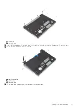
Страница 14: ...1 optical drive bezel 2 optical drive 3 optical drive bracket 4 screws 2 14 Replacing the optical drive ...
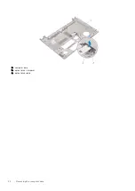
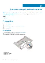
Страница 32: ...a computer base b optical drive interposer c optical drive cable 32 Removing the computer base ...
Страница 40: ...3 latch 4 screw 40 Removing the I O board ...
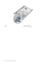
Страница 50: ...1 screw 2 power button board 3 tape 4 power button board cable 50 Removing the power button board ...
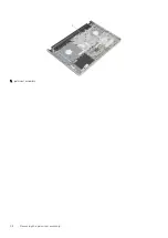
Страница 58: ...1 palm rest assembly 58 Removing the palm rest assembly ...
Страница 64: ...1 plastic scribe 2 camera cable 3 camera 4 display back cover 64 Removing the camera ...
Страница 70: ...a screws 12 b display hinges 2 c display back cover 70 Removing the display hinges ...
Страница 73: ...1 display cable 2 display back cover 3 camera cable 4 tape Removing the display cable 73 ...
Страница 76: ...1 display back cover and antenna assembly 76 Removing the display back cover and antenna assembly ...


