background image

24

English

Italiano

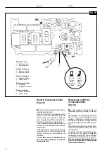
Uso del sensore (fig.19)

Sensore interno

■  

E' usato in tutti i tipi di installazione dove

il montaggio del comando venga effettua-
to a parete.
Per renderlo attivo occorre chiudere il ca-
vallotto JP1 montato sul circuito stampato
posto vicino al sensore. La sua posizione
all'interno della scatola è stata studiata in
modo che il sensore venga ventilato per
convenzione naturale (effetto camino)
minimizzando l'effetto del riscaldamento
dovuto ai componenti elettronici.

Sensore remoto

■  

E' usato in tutti i tipi di installazione dove

il montaggio del comando venga effettua-
to a bordo macchina.
Per renderlo attivo occorre aprire il caval-
lotto JP1 montato sul circuito stampato
posto vicino al sensore (questa operazio-
ne è effettuata dal costruttore della sche-
da elettronica per cui il comando ver-rà
consegnato configurato con JP1 aperto).

■  

Entrambi i sensori sono sempre montati

sulla scheda elettronica. In funzione del
tipo di applicazione usata verrà abilitato o
uno o l'altro tipo (tabella1).

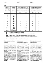
Uso dei cavallotti JP1 - JP2
(TAB I)

■  

Il comando tipo U non è provvisto di

cavallotto.

■  

I comandi tipo Y e T sono provvisti di un

cavallotto JP1 utilizzato dal costruttore
per la taratura del termostato e dall'instal-
latore per la selezione del tipo di sensore
(esterno o interno).
Nell'applicazione con montaggio del co-
mando a bordo macchina JP1 deve esse-
re aperto.
Nell'applicazione con montaggio del co-
mando a parete JP1 deve essere chiuso.
Entrambi i comandi tipo Y e T sono prov-
visti della funzione timer; questa funzione
è attiva quando il cavallotto JP2 è chiuso.
Con il cavallotto JP2 aperto si abilita il
comando a lavorare con regolazione sul-
l'acqua o con montaggio a parete.

■  

I comandi tipo R e S sono provvisti di un

cavallotto JP1 utilizzato dal costruttore
per la taratura del termostato e
dall'installatore per la selezione del tipo di
sensore (esterno o interno).
Nell'applicazione con montaggio del co-
mando a bordo macchina JP1 deve esse-
re aperto.
Nell'applicazione con montaggio del co-
mando a parete JP1 deve essere chiuso.
Entrambi i comandi tipo R e S non sono
provvisti della funzione timer, per cui il
cavallotto JP2 non è montato.

■  

Una visione completa dei tipi di instal-

lazione è riportata in TAB. 1

■ 

Nota: Tutti i comandi vengono forniti

nella configurazione standard con JP1
aperto e JP2 chiuso.

Sensor use (fig. 19)

Internal sensor

■  

This is used on all units with wall-

mounted control.
To activate the sensor, it is necessary to
close jumper JP1 mounted on the printed
circuit board near the sensor. Its position
inside the box has been selected to allow
sensor ventilation through natural
convection (chimney effect) minimizing
the heating effect from electronic
components.

Remote sensor

■  

This is used on all fan coils with unit-

mounted control.
To activate the sensor, it is necessary to
open jumper JP1 mounted on the printed
circuit board near the sensor (the sensor
is supplied by the electronic card manu-
facturer with JP1 already open).

■  

Both sensors are always mounted on

the electronic card. Depending on the
type of application used one of the two will
be activated (table1).

Jumper use JP1 - JP2
(TAB I)

■ 

Jumpers are not supplied on control

type U.

■  

Controls types Y and T include jumper

JP1, used by the manufacturer for
thermostat setting and by the installer for
sensor selection (outside or inside).
With unit-mounted controls JP1 must be
open.
If the control is mounted on the wall JP1
must be closed.
Both Y and T controls include the timer
function; this function is activated when
jumper JP2 is closed;
When jumper JP2 is open the control
works through water flow control or is wall-
mounted.

■ 

Control types R and S  include jumper

JP1 used by the manufaturer for
thermostat setting and by the installer for
sensor selection (outside or inside).
If the control is mounted on the unit JP1
must be open.
If the control is wall-mounted JP1 must be
closed.
Both R and S controls are not provided
with the timer function, therefore jumper
JP2 is not mounted.

■ 

A complete list of installation types is

given in Table 1

■ 

Note: All controls are supplied with

standard configuration, with JP1 open
and JP2 closed.

Содержание AWX

Страница 1: ...ecteurs Konvektorlüfter Fan coils AWX Installation and maintenance Installazione e manutenzione Mise en place et entretien Installation und Wartung Instalación y mantenimiento 001 L L O Y D S R E G I S TER QUALIT Y A S S U R A N C E ISO9001 ...

Страница 2: ...nstallation It is advisable to keep cabinet packed until installation is complete See figure 1 for cabinet installation Installation Before proceeding to unit installation it is recommended to assemble the acces sories according to instructions supplied with the kit For the installation of the unit mounted control remove the plastic lid on the intake grille control side fig 2 If a fresh air damper...

Страница 3: ...n la rejilla en el lado del mando fig 2 En el caso de que se quiera utilizar una compuerta de toma de aire externo es necesario efectuar una abertura en la pared como indicado en la fig 3 No colocar el fan coil en lugares en los que pueda producirse goteo de agua como per ejemplo ropa colgada para secar Empfang Prüfen Sie daß die Verpackung nicht beschädigt ist Packen Sie das Gerät aus und überprü...

Страница 4: ...e upper screws hook on the base unit and fix it with 4 screws To complete the installation make electric and water connections as per the diagram inside the electric panel Horizontal unit fig 5 Use the template supplied with the packaging for ceiling mounting of the unit Drill four holes for the screw anchors Hook the unit on the screw anchors in the ceiling and adjust the 4 screws in order to giv...

Страница 5: ... instalación efectuar las conexiones hidráulicas y eléctricas confor me al esquema indicado en el cuadro eléctrico Unidadhorizontal fig 5 Para instalar la unidad en el techo utilizar el patrón incluido en el embalaje Efectuar cuatro agujeros para los tornillos de sujección Enganchar la unidad en los tornillos de sujeccióncolocados en la pared y ajustar el cierre de los cuatro tornillos de manera q...

Страница 6: ... acces sibile e manovrabile con chiave da 10 mm o con cacciavite Le dimensioni sono Ø 3 4 GAS femmina per la batteria standard e Ø 1 2 GAS fem mina per la batteria di riscaldamento per impianti a 4 tubi Water connections Water piping can enter either from the floororfromthewall usingthespaceshown in fig 6 The unit coil can be supplied with water connections positioned as requested However field co...

Страница 7: ...u alojamiento encima del cuadro eléctrico fig nº 10 Las conexiones están fijadas en un alojamiento colocado en la parte lateral de la batería para evitar que se rompan mientras se conectan las tuberías de agua El enganche superior de la batería dispone de una válvula de escape de aire fácilmente accesible y manejable con llave de 10 mm o llave inglesa Las dimensiones son 3 4 GAS hembra paralabater...

Страница 8: ...lations A bipolar switch with 3 mm minimum distance between contacts with 4 A delayed fuse should be installed ahead of the feed line Earthing must always be provided Control panel The control panel is always posi tioned opposite the water connections It is possibile to connect cables to terminal board without lugs because it is equipped with screws for cable fixing N B Disconnect the power supply...

Страница 9: ...s datos eléctricos en la placa fijado en la unidad también la corriente necesaria para alimentar electrodomésticos y aparatos en uso Las conexiones eléctricas deben confor mar con los reglamentos y códigos nacionalesvigentes Se debe instalar un interruptor bipolar en la línea de alimentacíon con una distancia mínima de 3 mm entre contactos con fusible retardado de 4 A Hay que efectuar siempre una ...

Страница 10: ...l mantenimento in ambiente della tem peratura desiderata 4 Commutatore del ciclo di funziona mento ciclo estivo ciclo invernale fig 11 3 1 2 1 2 3 1 2 4 Control type U S T Y R Z ON OFF Three speeds Thermostat Electric heater Manual seasonal changeover switch Automatic seasonal changeover switch Centralized seasonal changeover switch Green LED summer function Red LED winter function Cooling heating...

Страница 11: ...se basse vitesse 3 Thermostat pour le réglage et le maintien de la température choisie 4 Commutateur du cycle de fonction nement été hiver Regelungstyp U S T Y R Z ON OFF ein aus Drei Drehzahlen Thermostat Elektroheizung Manueller Betriebsart Umschalter Automatischer Saison Umschalter Zentraler Saison Umschalter Grüne LED Sommerbetrieb Rote LED Winterbetrieb Kühl Heizventil Vierleiter Wärmetausche...

Страница 12: ...costruttore Cablaggio dell instalatore A Marrone B Blu C Nero D Azzurro G Grigio Y Giallo O Arancio R Rosso V Viola W Bianco Wall mounted control box Fig 12 Important Control box must be positionedhorizontally Refer to section Sensor use sub section Jumper use Remove the control box cover disconnect the cables from the terminal block and the cable from the sensor as they are no longer usable Place...

Страница 13: ...e neuen Elektroanschlüsse zwischen Regler und Gerät hergestellt werden Die Regelabteil Abdeckung wieder anbringen und mit den Schrauben befestigen Schaltplan Legende 1 Ventilatormotor 2 Motorkondensator 3 Regelabteil 4 Klemmbrett 5 Sensor 6 Ventil 7 Heizungswiderstand 8 Thermosicherung 9 Sicherheits Thermostat 10 Widerstandsrelais 11 Kaltwasserventil 12 Warmwasserventil 13 Saison Umschalter 14 Min...

Страница 14: ...gola zione sull acqua o con montaggio a parete Il comando tipo T deve essere completa to con uno dei seguenti collegamenti cambio stagionale a distanza fig 13 funzionamento solo in riscaldamento cavallotto tra i morsetti 7 e 5 funzionamento solo in raffreddamento cavallotto tra i morsetti 7 e 6 Control type T and Y function description fig 13 14 Control through fan When the thermostat demands heat...

Страница 15: ...sario quitar el perno en U JP2 colocado en el circuito impreso del mando El mando tiene dos indicaciones de funcionamiento la primera con una luz roja que indica el funcionamiento en invierno la segunda con una luz verde que indica el funcionamiento en verano Con el mando montado en la máquina cuando el ventilador está parado después de haber alcanzado el punto deseado se enciende el timer y conte...

Страница 16: ...locità termostato cambio stagionale a distanza Schema di collegamento per la regolazione della temperatura ambiente mediante controllo sulla portata d acqua Contrôle type T ON OFF 3 vitesses thermostat dispositif de changement été hiver à distance Système de contrôle de la température ambiante agissant sur la vanne Regelungstyp T ON OFF drei Drehzahlen Thermostat Saison Fernumschalter Anschlußplan...

Страница 17: ...ummer winter switch Control package to control room temperature through water volume Comando tipo Y ON OFF 3 velocità termostato cambio stagionale incorporato Schema di collegamento per la regolazione della temperatura ambiente mediante controllo sulla portata d acqua ContrôletypeY ON OFF 3vitesses thermostat inverseur manual été hiver Système de contrôle de la température ambiante agissant sur la...

Страница 18: ...l ventilatore Contrôle type Z ON OFF 3 vitesses thermostat inverseurmanualété hiver Système de contrôle de la température ambiante agissant sur le ventilateur Regelungstyp Z ON OFF drei Drehzahlen Thermostat eingebauter Saison Umschalter Anschlußplan für Regelung der Raumtemperatur durch den Ventilatormotor Mando de tipo Z ON OFF 3 velocidades termostato cambio de estaciónincorporado Esquema de co...

Страница 19: ...uementpar le moteur du ventilateur Un thermostat interrompt le fonctionnement du ventilateur lorsque la températurededépartdel eautombeen dessous de 35 C enclenchement à 45 C Dans ce cas la fonction du programmateur est elle aussi in terrompue En mode refroidissement été le thermostatdebassetempératuredel eau est mis hors tension Funktionsbechreibung des Regelungstyps Z Abb 15 Regelungstyp Z hat d...

Страница 20: ...l comando sono inserite due segnalazioni di funzionamento la prima visualizzata da una lampadina rossa che indica il funzionamento invernale la se condavisualizzatadaunalampadinaver de che indica il funzionamento estivo Control type S ON OFF 3 speed thermostat automatic summer winter changeover for electric heaters and 2 pipe unit Control package to control room temperature through electric heater...

Страница 21: ...eigt Description des fonctions de contrôle type S Fig 17 Le ventilateur tourne toujours à la vitessechoisie Laréglageduthermostat agit les vannes eau chaude et eau froide Iln yapasdetimervuqueleventilateur nes arrêtejamaissurcetypedecontrôle Le thermostat active de sortie eau froide ou chaude en choisissant automatiquement entre fonctionnement refroidissementouchauffage Le thermostat possède une z...

Страница 22: ...vernale la se condavisualizzatadaunalampadinaver de che indica il funzionamento estivo Entrambilelampadinesonolegatealfun zionamento del termostato Nellacondizionedifunzionamentoinver nale aset pointsoddisfatto lalampadina rossa è spenta viene accesa quando il termostato chiede caldo Nella condizione di funzionamento esti vo a set point soddisfatto la lampadina verde è spenta viene accesa quando i...

Страница 23: ...ption des fonctions de contrôle type R fig 18 Dans les deux applications le ventilateur continue à tourner à la vitesse choisie tandis que le réglage du thermostat est différent L une exige le réglage sur les résistances électriques et surlavanneeaufroidel autresurlavanne eau chaude et froide Il n y a pas de timer vu que le ventilateur nes arrêtejamaissurcetypedecontrôle Le contrôle type R possède...

Страница 24: ... con montaggio del co mando a parete JP1 deve essere chiuso Entrambi i comandi tipo R e S non sono provvisti della funzione timer per cui il cavallotto JP2 non è montato Una visione completa dei tipi di instal lazione è riportata in TAB 1 Nota Tutti i comandi vengono forniti nella configurazione standard con JP1 aperto e JP2 chiuso Sensor use fig 19 Internal sensor This is used on all units with w...

Страница 25: ...oenla máquina JP1 tiene que estar abierto Enlaaplicaciónconcontrolmontadoenla pared JP1 tiene que estar cerrado Ambos mandos de tipo Y y T disponen de la función timer esta función se pone en marcha cuando el puente JP2 está cerrado Con el puente JP2 abierto el mando funciona mediante regulación de agua o con montaje en pared Los mandos de tipo R y S tienen un puente U JP1 utilizado por el fabrica...

Страница 26: ...to Sensore interno Fiche électronique Sonde à distance Sonde interne Elektronische Karte Fernsensor Eingebauter Sensor Ficha electrónica Sensor a distancia Sensor interno Resistenze elettriche di riscaldamento fig 20 Le unità possono essere fornite con resistenze elettriche installate in fabbri ca Le resistenze controllate dal comando tipo R o S e da relé ausiliario sono cablate in fabbrica e rich...

Страница 27: ... resistencia eléctrica Fig 20 La unidad puede suministrarse con un calentador eléctrico instalado de fábrica Los calentadores eléctricos controlados por el mando tipo R o S desde un relé auxiliar están cableados de fábrica y requieren un siministro de potencia separado y protección suficiente por me dio de fusibles y ruptores de circuito automáticos Los dispositivos de protección suministrados con...

Страница 28: ...o del tipo ad azionamentotermicoalimentatea230V consumo 3VA la massima pressione di lavoro è di 600 kPa Il tempo di apertura dipende dalla temperatura ed è pari a 120 240secondi La tenuta dei raccordi alle valvole è ga rantita da una guarnizione in gomma in serita nel raccordo coppia di serraggio 2 5 kgm L accessorio valvole automatiche può inoltre essere fornito con rubinetto e de tentoreperlareg...

Страница 29: ...insérée dans le raccord couple de serrage 24 5 Nm Cette soupape automatique accessoire peut en outre être fournie avec robinet et dépresseur pour la régulation du débit de l eau et isoler l unité du reste du circuit La soupape automatique peut être à 3 voies avec bipasse ou à 2 voies Pour connaître l emplacement précis des raccords consulter le Manuel de Sélectionoulegabaritfourniavecchaque unité ...

Страница 30: ...opo aver tolto la griglia di mandata aria facendo attenzione a non danneggiare le alette Motore Il motore è lubrificato a vita Non è pertanto necessaria alcuna lubri ficazione periodica Checks before starting Unitshallnotbestarteduntilallsystem piping has been cleaned and all air has been purged Check condensate drain pipe slope Make sure that air filter is clean and properly installed Compare vol...

Страница 31: ... anderen Verun reinigungen Der Filter sollte einmal im Monat kontrolliert werden oder öfter falls sich das Gerät in einem staubigen Umfeld befindet Ein verunreinigter Filter reduziert die Wirksamkeit des Gerätes Den Filter aus dem Gerät entfernen Mit Wasser und Reinigungsmittel oder mit einem Staubsauger vorsichtig säubern Den Filter einsetzen und in seiner Lage positionieren Der Filter sollte vor...

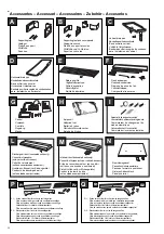
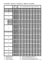
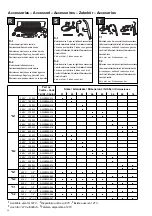
Страница 32: ...ires Zubehör Accesorios A Supporting feet Sostegni Pieds de support Stützfüße Soportes B Supporting feet and cover panels Sostegni e zoccoli Pieds de support et socles Stützfüße und Fußleisten Soportes y zócolos D Horizontal drain pan Bacinella ausiliaria orizzontale Bac auxiliaire horizontal Horizontale Ablaufwanne Bandeja auxiliar recogida de condensados para instalación en horizontal Fresh air ...

Страница 33: ...00A113 AWX001A110 N AWX003A111 AWX006A112 AWX008A113 AWX001A301 AWX001A302 P1 AWX001A303 AWX001A304 AWX001A306 AWX001A307 P2 AWX001A308 AWX001A309 AWX001A311 Q1 AWX001A312 AWX001A313 AWX001A314 Q2 AWX001A315 AWX001A316 Part no Codice Code Teil Nr Còdigo Accessories Accessori Accessoires Zubehör Accesorios Available also for 127V Only on units manufactured from January 1997 Disponibile anche a 127V...

Страница 34: ...r Anschluß links Válv mot bat 2 tubos conex izq S 2 Motorized valve 2 pipe coil right hand connections Valvola motorizzata batteria 2 tubi attacchi destra Kit vanne pour battérie 2 tubes conn droit Ventil mit Stellantrieb Zweileiter Wärmetauscher Anschluß rechts Válv mot bat 2 tubos conex der T 1 Motorized valve 4 pipe coil left hand connections Valvola motorizzata batteria 4 tubi attacchi sinistr...

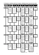
Страница 35: ...istenza elettr no A alta potenza B bassa potenza Grandezza 1 01 2 02 3 03 4 04 5 05 6 06 8 08 0 10 Versione S standard 230V H alta prevalenza 230V A standard 127V B alta prevalenza 127V Batteria F 2 tubi sinistra G 2 tubi destra C 4 tubi sinistra D 4 tubi destra E espansione diretta sinistra L espansione diretta destra H alta potenza sinistra K alta potenza destra AWX 4 M S F Y V Resistencia eléct...

Страница 36: ...dell avviamento 30 Manutenzione 30 Accessori 32 Identificazione dell unità 35 SOMMAIRE Réception 3 Préparation de l unité 3 Mise en place 3 verticale au sol 5 verticale au mur 5 horizontale 5 Connexions hydrauliques 7 Drainage de l eau de condensation 9 Connexions électriques 9 Panneau électrique 9 Contrôles 10 fonctions 11 contrôle mural 13 contrôle type T et Y 15 contrôle type Z et U 19 contrôle...

Отзывы: