


7
Example: There are 4 transmitters connected to the controller with a consuption of 60 mA each. The controller has a consuption of 300mA.
The remaining 7,46 A (I=8000-300-4x60) are used to supply the visual and acoustic alarms.
Information on the constuption of each transmitters and components of the visual and acoustic alarms is given in the
respective manuals.
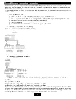
Warning: never connect the supply voltage 24V and 230V simultaneously
7.
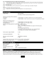
Output relay
Each relay can by default be configured to activate on any number and any combination of events:
Transmitter:
4 levels of gas leek alarms, PEL, STEL, transmitters malfunction
Controller:
2 levels of temperature, flooding, controller malfunction, 2 levels of exceeded temperature, flooding indication
Relays can after activations be configured for the following output functions: normally closed, normally open, cycling of
open/close, automatic deativation of deactivatable outputs after a certain time or after pressing a button.
Specific configurations of the relays are given in the configuration protocol provided to the controller
8.
Regulating the supply voltage
Pomocí trimru můžeme regulovat výstupní napětí zdroje v rozsahu 22-26V.
V případě že jsou snímače připojeny na velkou vzdálenost, může být pro správnou funkci nutné zvýšit
napájecí napětí.
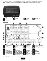
Controls
The control panel is equipped with a segmented LCD display and can be controlled using the LEFT, RIGHT and ENTER buttons.
In Basic mode the controller displays the concentration and the states of the configured channels. Digital channels
(transmitters connected via RS485) are numbered 1 to 32, and analog channels (connected via current loop) are in the range
of 41 to 48. The controller sequentially switches between the configured channels (basic interval 3s). For a longer display of a
specific channel, briefly press ENTER (the channel remains displayed for 30s). The ENTER button also serves as a confirmation
key for switching-off of the off-switchable outputs of the controller. The respective output remains in the defaul state for as
long as there is no fading of the event that triggered it (concentration drop, disappearance of the error code).
1.
Panel
LCD display
Indication of proper
operation of the
controller
Gas leek
LEFT button (move through
menus, switch between
transmitters)
RIGHT button (move
through menus, switch
between transmitter)
ENTER button
(unblocking of the
acoustic alarms and
thelatch function,
confirm)
6
5
4
3
2
1