background image

SENTINEL 3

56

13.COMPLETE MONITOR GUIDE

13.1 BUTTON FUNCTIONS AND CONNECTIONS

13.1.1 MONITOR 

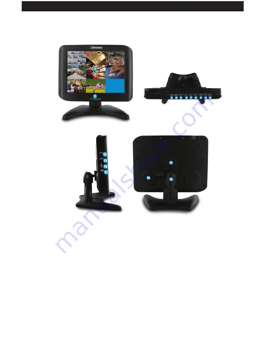
1. 

LCD Screen


Watch your footage.

2. 

Power Button


Turn LCD Monitor On / Off.

3. 

Mute Button 

4. 

Menu Button


Enters the on screen menu.  

5. 

Down Arrow Button 


Navigates the on screen menu.

6. 

Up Arrow Button


Navigates the on screen menu.

7. 

Volume Decrease Button

8. 

Volume Increase Button

 9. 

Auto Button


Automatically cycles through both 


input channels.

10. 

Pics Button Changes 


picture setting.

11. 

AV1/AV2 Button


Switch input channels.

12. 

AV2 In Port Connection to video 


input source. 

13. 

AV1 In Port Connection to video 


input source. 

14. 

3.5mm Headphone Jack 


Connects to stereo  headphones.

15. 

Power Input DC power 


input (12V)

16. 

Speakers

17. 

Mounting Rails

18.  

Mounting Hole 

Содержание SENTINEL 3

Страница 1: ...t Accessible 8CH DVR w 8 Hi Res Indoor Outdoor Night Vision Cameras and 8 LCD Monitor Deluxe Internet Accessible 8CH DVR w 8 Hi Res Indoor Outdoor NightVision Cameras and 8 LCD Monitor Model SENTINEL 3 Version 1 0 www defender usa com ...

Страница 2: ...f this warranty 5 The warranty expressly provided for herein is the sole warranty provided in connection with the product itself and no other warranty expressed or implied is provided Defender assumes no responsibilities for any other claims not specifically mentioned in this warranty 6 This warranty does not cover the shipping cost insurance or any other incidental charges 7 You MUST call Defende...

Страница 3: ...U SETUP DESCRIPTION 22 6 1 DATE TIME SETUP 23 6 2 CAMERA SETUP 24 6 2 1 EDIT CAMERA TITLE 1 8 24 6 2 2 VIDEO ADJUST 24 6 2 3 MOTION DETECTION 25 6 3 RECORD SETUP 26 6 4 SCHEDULE SETUP 27 6 5 HARD DISK SETUP 28 6 6 CF CARD SETUP 28 6 7 OTHERS 30 6 7 1 PASSWORD 31 6 7 2 BUZZER 31 6 7 3 RELAY OUTPUT Advanced users 32 6 7 4 ALARM INPUT Advanced users 33 6 7 5 SEQUENCE DWELL TIME 34 6 8 FACTORY DEFAULT...

Страница 4: ...UNCTIONS AND CONNECTIONS 56 13 1 1 MONITOR 56 13 1 2 REMOTE CONTROL 57 13 2 INSTALLATION 58 13 2 1 OPTION 1 CONNECTING TO SECURITY CAMERAS 58 13 2 2 OPTION 2 CONNECTING TO A DVR 59 13 2 3 POWERING ON 60 13 2 4 BASIC OPERATION 60 13 2 5 ADJUSTING SETTINGS 60 13 2 6 PICTURE 60 13 2 7 OPTION 61 13 2 8 CLOCK 61 13 2 9 SYSTEM 61 13 2 TROUBLESHOOTING 62 14 COMPLETE SPARTAN1 GUIDE 63 14 1 FEATURES OF THE...

Страница 5: ...Quickly search your recorded footage by date and event 11 Menu Button 12 Exit Info Button Return to the previous menu view system information Software CD 10 RCA to BNC Connectors 1 Remote Control for LCD Monitor 10ft RJ45 Ethernet Cable 8 Ultra Slim LCD Monitor 8 Camera Mounts w Hardware 8Indoor Outdoor Night VisionCCDCameras 1 DVR 250GB HDD 1PowerAdapterforLCD Monitor 1 Power Adapter for DVR Onli...

Страница 6: ...camera channels 2 2 REAR PANEL 1 BNC Video Inputs Connects the cameras to the DVR 2 Power Input DC power input 12V 3 Alarm Input Output Port 4 RCAAudio Input For connecting a microphone audio supported camera not included 5 RCA Audio Output For connection to your TV monitor 6 BNC Video Output For connection to your TV monitor 7 Ethernet Port For connection to your local area network and Internet 8...

Страница 7: ...red IR LEDs allows the camera to see in the dark up to 15ft away 3 CDS Sensor turns on the infrared LEDs when it gets dark out 4 Camera Housing made of anodized aluminum to prevent rust 5 Camera Mount allows the camera to be desk or wall mountable 6 Connection to Video Power Wire Converts to RCA ...

Страница 8: ...utton Enters the on screen menu 5 Down Arrow Button Navigates the on screen menu 6 Up Arrow Button Navigates the on screen menu 7 Volume Decrease Button 8 Volume Increase Button 9 Auto Button Automatically cycles through both input channels 10 Pics Button Changes picture setting 11 AV1 AV2 Button Switch input channels ...

Страница 9: ...re currently viewing 9 Timer Adjust timer settings 10 Language Select the desired language 11 Calendar Enter the onscreen calendar 12 AV Switch between video inputs 13 Flip Image Horizontally 14 Flip Image Vertically 12 AV2 In Port Connection to video input source 13 AV1 In Port Connection to video input source 14 3 5mm Headphone Jack Connects to stereo headphones 15 Power Input DC power input 12V...

Страница 10: ...desk table top If wall mounting use the mounting hardware in the package Each camera comes with 60 feet of extension wire Please make sure you mount the cameras no more than 60 feet from the DVR We recommend using a surge protected power bar and or an Uninterrupted Power Supply UPS to power the DVR and camera system Mounting 1 Screw each mounting bracket into each camera s mounting hole turning it...

Страница 11: ...n of each camera 1 Plug the 4pin din female connection on the camera into the 4 pin din male connection on the 60 foot video power wire 2 Plug the camera s power supply into the power jack located on the 60 foot video power wire 3 Plug the camera s power adapter into an AC outlet ...

Страница 12: ... the 60ft video power wire s male RCA plug to VIDEO IN port for channels 1 8 3 2 MONITOR INSTALLATION 3 2 1 CONNECTING TO DVR 1 Plug the 3 5mm to RCA female wire into the AV1 IN port on the monitor 2 Plug one end of an RCA wire into the DVR s VIDEO OUT port Plug the other end into the female end of the 3 5mm to RCA female wire ...

Страница 13: ... Press the POWER button on the front of the unit 4 Your cameras DVR should now be displayed on the LCD 3 3 AUDIO INSTALLATION 1 If you have an audio supported camera or microphone with an RCAAudio Out connection you may connect it to the Audio In port on the DVR 2 Connect an RCA audio wire not included to one of the Audio Out ports on the DVR 3 Connect the other end to the Audio In port of your TV...

Страница 14: ...errupted Power Supply UPS backup To turn the DVR on and off use the power switch on your UPS or power bar This DVR does not have a power switch This is for your security and helps to prevent users from accidentally turning the DVR off The DVR will power on and you will see a boot screen After the DVR initializes your cameras should be displayed and recording will begin immediately NOTE Spot montor...

Страница 15: ...ERATION 4 1 BASIC OPERATION 1 Manual Switching Video Inputs Press theAV button on the remote to switch between video inputs 2 Press theAUTO button on the monitor to activate auto mode which will automatically cycle between both inputs Pressing it once will set the cycle interval to 4 seconds Pressing it again will set the cycle interval to 6 seconds Pressing it a third time will set the cycle inte...

Страница 16: ...e monitor to turn off select it and press the volume down button to adjust the hour Press the volume up button to adjust the minute 6 The attention mode time allows you to set up a flashing ATTENTION message that will notify you in advance before the monitor turns off You must have the off time set to use this function Set the attention mode time a few minutes before the off time To set it up sele...

Страница 17: ...tton to turn Sequence Mode on or off Full screen channel auto sequence will skip the channels that show video loss i e the cameras that are unplugged or not powered on 7 When video loss occurs a video loss message will be shown on the screen 8 During an alarm triggered event the corresponding channel name will be changed to the color red 9 During a motion triggered event the corresponding channel ...

Страница 18: ...SENTINEL 3 18 ...

Страница 19: ...ely from a 3rd party and DEFENDER does not offer support on motion sensors This feature is for advanced users only If you have alarm sensors wired correctly the alarm record function will allow you to specify which hours of the day you want to record when your alarm sensor is triggered After your alarm is triggered the system will record for a duration that you specify During this time you cannot ...

Страница 20: ...ll screen CH1 CH8 6 Press the SPLIT button to switch to Full Screen Quad Screen 9 Split Screen 7 The SEQ button does not function during playback 8 Press the PAUSE button under normal playback to pause 9 During pause status press the LEFT button to step rewind playback and the RIGHT button to step forward playback 10 During normal playback press the LEFT button to adjust the rewind playback speed ...

Страница 21: ...Green Index Bar Recorded data available under this date period 4 MINUTE White Color Bar No recorded available under this time period Red Color Bar Manual recorded data motion detection recorded data andalarm recorded data is available under this time period Blue Color Bar Schedule recorded data is available under this time period 6 Use the UP DOWN buttons to move the cursor to the desired item YEA...

Страница 22: ...assword is requested after the MENU button is pressed 1 In order to enter the main menu the password entered must be correct After entering the main menu all recording activities will stop 2 Default Password 11111111 CH1 CH8 represents number 1 8 ...

Страница 23: ...SENTINEL 3 23 6 1 DATE TIME SETUP DATE FORMAT Three Types of Date Format Setup 1 Y M D Year Month Day 2 M D Y Month Day Year 3 D M Y Day Month Year ...

Страница 24: ...he desired camera number by using the UP DOWN buttons 3 Move between the characters of the camera title by using the LEFT RIGHT buttons and use UP DOWN buttons to edit the camera title letters A Z numbers 0 9 or blank spaces 6 2 2 VIDEO ADJUST Adjustable brightness contrast saturation and hue for 1 8 CH videos ...

Страница 25: ...y in an area on your camera you can block that area from detecting motion Use the directions below to set up motion detection areas Area Block Color Grey Detection Block These areas will be detected Transparent Non Detection Block Green Flashes when motion on the camera is being detected Use the green flashes to determine where motion is consistently being detected and then make sure to set the mo...

Страница 26: ... camera channel to avoid false triggering of motion record 6 3 RECORD SETUP 1 QUALITY LOW MEDIUM HIGH 2 AUDIO ON Audio recording enabled OFF Audio recording disabled 3 DISK FULL Overwrite When the hard disk is full the system overwrites your oldest recorded footage recommended Stop When the hard disk is full the system stops recording message will be displayed 4 POST ALARM Recording time after an ...

Страница 27: ...just the letter to the one that represents the type of recording you would like For example if you want to record only when motion is detected at 12 00 PM move the cursor to the 12 and use the arrows to change the letter to M All types of recording are listed below along with their corresponding letter 1 C Continuous Recording 2 M Motion Detect Record 3 A Alarm Recording advanced users only 4 None...

Страница 28: ...ed material and when no recorded materials are available current date is displayed 3 FORMAT Format the HDD Warning This will erase all your recorded footage 6 6 CF CARD SETUP 1 CF TOTAL CAPACITY Total Capacity 2 CF REMAIN CAPACITY Remaining Capacity 3 CF CARD COPY Copy the selected file to the CF card 4 FORMAT Delete all data stored in the CF card ...

Страница 29: ... the start and end time of the desired video clip 4 COPY Select COPY to start copying to your CF card When the data size selected exceeds the storage capacity of the CF card it will start copying from the beginning and stop when the CF card is full Each channel and event generates a different AVI file Windows Media Player supports AVI file playback File size is 720X240 When using a computer to pla...

Страница 30: ...ed before entering the main menu 2 KEY STOP BUZZER RELAY Use this option if you have an external relay device attached advanced users When the buzzer or relay device is triggered by an event enabling this setting will allow you to press any key to deactivate 3 COLOR BAR By using the color bar the user may adjust the color of the monitor 4 LANGUAGE Select the desired language ...

Страница 31: ... password is stored on the CF card after inserting the CF card the password will not be requested by the system 2 Default Password 11111111 CH1 CH8 represents number 1 8 3 Press the ENTER button to enter new password confirm settings and press EXIT button to exit 6 7 2 BUZZER BUZZER ON Buzzer is enabled OFF Buzzer is disabled ...

Страница 32: ... users The installation of any relay output alarm is optional and DEFENDER cannot offer technical support on such alarms Contact the alarm sensor manufacturer for more information RELAY OUTPUT Arelay output can be connected to an external sounding device or warning device Two Types NO NC of Relay Output Setup ON Relay output enabled OFF Relay output disabled PERIOD Duration time of the relay outpu...

Страница 33: ...urer for more information Sensor Type NC Normal Close NC Alarm Setup NC Normal Close the alarm will be triggered during NC status NO Normal Open NO Alarm Setup NO Normal Open the alarm will be triggered during NO status All EACH Alarm input can be individually setup to NC or NO DISABLE Disable alarm input can be individually setup C All alarm input is setup to NC O All alarm input is setup to NO ...

Страница 34: ... 2 SPOT MONITOR Specify how long video will be displayed on the SPOT monitor when motion is detected 3 SPOT MONITOR ALARM Specify the dwell time for the spot monitor alarm 6 8 FACTORY DEFAULT To return to factory default settings select the YES option and then press ENTER to load the factory defaults Press EXIT to exit ...

Страница 35: ...o a router If you are using a DSL internet connection the setup process is much easier if you use modem with a router integrated in it as this will help avoid any problems connecting your DVR Please write down the model of your router in the important information section A PC laptop or computer that is connected to the router so you can make the necessary changes This system is not Mac compatible ...

Страница 36: ...en will open 2 Select the SECURITY tab then click on the CUSTOM LEVEL button in this tab 3 Change the ActiveX settings to the ones seen in the images Download signed ActiveX controls PROMPT Download unsigned ActiveX controls PROMPT Initialize and script ActiveX controls not marked as safe PROMPT Run ActiveX controls and plug ins ENABLE Script ActiveX controls marked safe for scripting ENABLE if it...

Страница 37: ...asking if you want to block or unblock this program Click Unblock 4 Click on the UPDATE button In the top left area of the program window you should see a set of numbers This is the IP address of your DVR Write it down in the information area of this manual listed as ROUTER IP 5 Open up Internet Explorer In the Address bar enter your DVR s IP address found in Step 4 followed by a space a colon and...

Страница 38: ... listed in the Port Forwarding section PORT FORWARDING Port forwarding is a necessary step that opens a path on your home business network to allow you to view your DVR video feed from outside your network over the internet There are hundreds of makes and brands of routers on the market and these instructions have been made using a D Link router Model DI 524 If you have a router that is different ...

Страница 39: ...ing the port range forwarding screen With some D LINK routers the port forwarding screen is located within the Applications Games or Filters tab in others it is located in the Advanced Tools tab 1 Open your web browser Enter the ROUTER IP address in the address bar as shown below and press ENTER 2 Enter the user name admin Leave the password blank followed by pressing the OK button unless you have...

Страница 40: ...owing 2 examples 14 14 243 113 2000 OR 14 14 243 113 2000 2 Press ENTER and your DVR s login window should pop up If it does not pop up your router is not properly forwarding the necessary port This could be due to a number of problems including incorrect settings presence of a firewall or a DSL modem that has its own IP address 4 Select the Virtual Server tab Enable the Virtual server In the Name...

Страница 41: ...Agree to the Terms of Service by checking the boxes Click Create Account If your DSL modem has its own internal IP address it will not properly forward the necessary port You may have to configure PPPoE settings in the DVR to match the settings provided to you by your Internet Service Provider ISP Consult your ISP for more information DEFENDER technical support cannot troubleshoot modems since cha...

Страница 42: ... take up to 24 hours to arrive in your inbox If you cannot find the message in your inbox please check your junk spam mail folder 6 When you click the link a window will appear that displays Account Confirmed Click on the login link and enter the user name and password you created 8 Click on the Dynamic DNS link 7 Click on the Services button located on the top menu ...

Страница 43: ...your first name or company name 11 Choose a domain name from the dropdown menu We recommend using the dvrdns org suffix 12 In the IP address field type in your external IP address it may also be shown below the field 13 Leave all the rest of the options as is and click Create New Host 14 Your dynamic DNS settings have been created ...

Страница 44: ... only need to type in your domain name in order to access your DVR whether you are inside or outside of your network 1 Log on to your DVR through your computer by using either the internal or external IP address 2 Click the CONFIGURATION button 3 Under the Network DVR Setup window scroll down to DDNS Account Setting 4 Make sure the ENABLE button is selected 5 Entertheusername password andfulldomai...

Страница 45: ...o both at the same time Please make sure that you press STOP before proceeding My browser keeps freezing First make sure you have an up to date browser and that the proper ActiveX options are selected If they are you may need to re install your browser I can t remember my DVR s password Call technical support to obtain the DVR s master password I can t see at night with my IR night vision camera T...

Страница 46: ...SENTINEL 3 46 8 FUNCTION SETUP 8 1 MAIN DISPLAY Optimal browsing resolution is 1024 x 768 Live Display Move the cursor inside the image range and right mouse click to display the following menu ...

Страница 47: ... Bar Reveals current status 8 1 2 IMAGE RECORDING This mode allows you to save picture or video files from the DVR to your computer Image Recording Setup Display 1 Save as JPEG Save as picture file 2 Save as AVI Save as AVI animation file Note To prevent asynchronous AVI recording both functions should not be simultaneously selected ...

Страница 48: ...arting with DVR_1 DVR_2 and so on 8 1 2 2 SAVE AS AVI No Limit Unrestricted video storage continuous avi recording Number Video storage according to number of frames For example if set to 50 50 frames will be stored per avi file Save interval Video storage according to one tenth of a second For example if you enter 10 then one file is stored per second If you enter 50 then one file is stored every...

Страница 49: ...Toggle Confirm Button Message Display Toggle 10 ENTER DISP Return to Previous Menu System Information Display Toggle Confirm Button Message Display Toggle 11 UP DOWN Up Directional Button Channel Up Button Down Directional Button Channel Down Button 12 CH Camera Select Button CH1 8 Resolution Setting 176x144 352x288 704x576 120x160 320x240 Pre set Value 640x480 Quality Setting High Middle Low Pre ...

Страница 50: ...Configuration Advanced Setup this function can only be adjusted by the administrator i e the user name must be admin Live Video Back to live video display Record Please refer to 9 1 2 Image Recording Snapshot Press this button to capture one live image and press RIGHT button to store the image Audio Live audio control On Off Default OFF ...

Страница 51: ...etup 8 2 1 ADVANCED NETWORK SETTING 1 LAN Setting LAN IP address setting is the same as IPEdit 2 DHCP Select item Automatically by DHCP to get an IP address 3 DNS Static IP users needs to setup an IP address If you do not know your static IP settings contact your Internet Service Provider ...

Страница 52: ...ss the DVR These users will be able to view live display record and capture images However they will not be able to change configuration settings When you have set up user accounts be sure to write down the user name and password for each account so you can provide the users with the appropriate login credentials Authorization Specify whether authentication is needed to access the DVR If you selec...

Страница 53: ... to detect the DVR s IP Address Please check your firewall or antivirus software Some software may block IP edit from accessing the network In Windows Firewall you may have to add IPedit exe to the exceptions list Reconnect the Ethernet cable See the network guide for more troubleshooting tips 9 2 CAMERA TROUBLESHOOTING No picture signal Make sure your TV monitor is on the correct video input chan...

Страница 54: ...han 15ft away may vary based on amount of ambient light available If using during the day your camera may not be getting enough light Adjust the sunshade by sliding it backwards to let in more light Check the brightness and contrast settings on your TV monitor If your camera is connected to a VCR DVR check the brightness and contrast settings on the VCR DVR Move your camera to another location Nig...

Страница 55: ...please enter the main menu to stop all HDD activities then power off the device before replacing the hard disk 12 APPENDIX 12 1 DB25 ALARM INPUT RELAY OUTPUT DEFINITION Pin Definition Pin Definition Pin Definition Pin Definition 1 ALARM 1 2 ALARM 2 3 ALARM 3 4 ALARM 4 5 GND 6 ALARM 5 7 ALARM 6 8 ALARM 7 9 ALARM 8 10 GND 11 12 13 14 15 16 17 18 19 20 21 RELAY OUT COM 22 RELAY OUT N C 23 RELAY OUT N...

Страница 56: ...6 Up Arrow Button Navigates the on screen menu 7 Volume Decrease Button 8 Volume Increase Button 9 Auto Button Automatically cycles through both input channels 10 Pics Button Changes picture setting 11 AV1 AV2 Button Switch input channels 12 AV2 In Port Connection to video input source 13 AV1 In Port Connection to video input source 14 3 5mm Headphone Jack Connects to stereo headphones 15 Power In...

Страница 57: ...en menu and adjust settings 6 Channel Down Down Navigation 7 Call Display the input channel you are currently viewing 8 Timer Adjust timer settings 9 Language Select the desired language 10 Calendar Enter the onscreen calendar 11 AV Switch between video inputs 12 Flip Image Vertically 13 Flip Image Horizontally ...

Страница 58: ...tput plug into the video input yellow end of the 3 5mm to RCA female wire 3 Repeat steps 1 and 2 for connecting a second camera to the AV2 IN port on the monitor 4 If the camera supports audio ensure that the RCA audio cable of the camera red or white is connected to one of the audio inputs red or white on the 3 5mm to RCA female wire 5 Ensure that the cameras are plugged in ...

Страница 59: ... your VIDEO OUT port is a BNC connection which is common in DVR units you will need to attach the BNC to RCA adapter before connecting the monitor 3 If the DVR supports audio ensure that an RCA audio cable is connected to the DVR s AUDIO OUT and that the other end red or white is connected to one of the audio inputs red or white on the 3 5mm to RCA female wire Make sure that audio is enabled on th...

Страница 60: ... between both inputs Pressing it once will set the cycle interval to 4 seconds Pressing it again will set the cycle interval to 6 seconds Pressing it a third time will set the cycle interval to 8 seconds Pressing it a fourth time will turn off auto mode 13 2 5 ADJUSTING SETTINGS Press the menu button to display the following options PICTURE OPTION CLOCK SYSTEM 13 2 6 PICTURE 1 Press the menu butto...

Страница 61: ...wn button to adjust the hour Press the volume up button to adjust the minute 5 To adjust the off time the time you want the monitor to turn off select it and press the volume down button to adjust the hour Press the volume up button to adjust the minute 6 The attention mode time allows you to set up a flashing ATTENTION message that will notify you in advance before the monitor turns off You must ...

Страница 62: ...wered on No sound Ensure that the camera DVR connected supports sound and that sound is enabled on the camera DVR Check all connections to ensure that the RCA Audio cable is connected to the monitor Make sure that the volume is not turned down or muted on the monitor or DVR camera Upside down or inverted picture Press the horizontal vertical flip buttons to fix the picture Distorted Color Too Brig...

Страница 63: ... wire to fit with a different video connection type Any unauthorized modifications will void your warranty 14 2 CAMERA INSTALLATION THINGS TO CONSIDER BEFORE YOU INSTALL YOUR CAMERA The camera should be installed between 8 and 13ft above the area to be monitored Ensure there are no obstructions in the camera s view to maximize viewing area Ensure that the sunshade is positioned to avoid glare and ...

Страница 64: ... pin DIN female connection on the camera into the 4 PIN DIN male connection on the 60ft video power wire 2 Match the two arrows on top of bothconnecting cables 3 Plug the camera s power supply into the power jack located on the 60ft video power wire 4 Plug the camera s power adapter into an AC outlet 5 Connect the 60ft video power wire s male RCA plug to the VIDEO IN port of your TV monitor VCR DV...

Страница 65: ... Live Frame Rate 120FPS Live Display Single Quad 9 Split Network Protocol TCP IP HTTP PPPoE DNS DDNS DHCP SMTP Network LAN IP Dynamic Static Network Connection 10 100 BaseT Ethernet RJ 45 Back up CF Card Max 4GB Play Search Mode Time Date Event List Play Speed Fast Forward x1 x2 x4 x8 x16 x32 x64 Play Mode Single Quad 9 Split OSD and System Menu Display Yes OSD Language Display Multi Language Time...

Страница 66: ...0 L R 60 On Off Timer Yes Sleep Timer Yes Languages English Russian German Italian Chinese Dutch Japanese Spanish Portuguese French Adjustable Screen Settings Contrast Brightness Color Sharpness Tint Speaker Wattage 0 3W x 2 LED Indicators Power Housing Material Plastic Housing Color Midnight Black Power Input DC 12V 1200mA Power Adapter Input AC 100 240V switching adapter Operating Temperature 32...

Страница 67: ...c Shutter 1 60 1 100000 sec BLC No AGC Automatic ELC Automatic Line Lock No Iris Control No White Balance Automatic Sun Shield Yes IR Cut Filter No Housing Material Anodized Aluminum Housing Color Midnight Black Signal Noise Ratio 48dB Camera Bracket Yes Operating Temperature 14 F 122 F Operating Humidity 98 Camera Power Input DC 12V 300mA Power Adapter Input 120V 60Hz LED Power Indicator No Dimen...

Страница 68: ...ewards are paid for tips that lead to the arrest and indictment of people charged with felony offenses and to date Crime Stoppers statistics show a conviction rate of approximately 95 To receive more information about Crime Stoppers or to make a charitable donation please fill in the fields on the back of this page cut on the dotted line and mail in PLACE POSTAGE HERE CRIME STOPPERS INTERNATIONAL ...

Страница 69: ...rtise a local telephone number which anonymous persons can call with information regarding a crime Callers tipsters may be eligible for a cash reward for their information If your community does not have a Crime Stoppers program and would like information about starting one return this card with the following information NAME ______________________________________PHONE _ __________________________...

Страница 70: ...f defender products for any illegal activities Defender is not responsible or liable in any way shape or form for any damage vandalism theft or any other action that may occur while a Defender product is in use by the purchaser Model SENTINEL 3 www defender usa com ...

Отзывы: