Figure 4.3:
The PILATUS3 S 6M detector with the cover removed (front view)
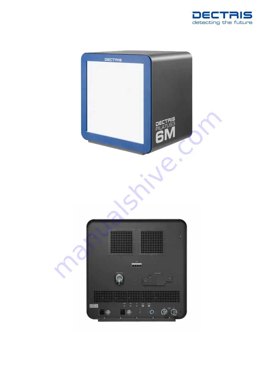
4.1.3. Back Side of the Detector
Figure 4.4:
The PILATUS3 S 6M detector (back view)
PILATUS3 S 6M Technical Specifications v1.1.1
10 | 25
Страница 1: ...Technical Specifications PILATUS3 S 6M Detector System Document Version v1 1 1 DECTRIS Ltd 5405 Baden Daettwil Switzerland www dectris com...
Страница 2: ...Document Version v1 1 1 Copyright 2019 DECTRIS Ltd...
Страница 3: ...7 4 DETECTOR DIMENSIONS AND CONNECTORS 8 4 1 PILATUS3 S 6M Detector 8 4 1 1 Technical Drawing 8 4 1 2 Front Side of the Detector 8 4 1 3 Back Side of the Detector 10 4 1 4 Status LEDs 11 4 1 5 Connect...
Страница 4: ...ted 20 7 2 Start up Procedure 20 7 3 Turning Off the Detector 21 7 4 Storing the Detector 21 7 5 Cleaning and Maintenance 21 8 TROUBLESHOOTING 22 9 CERTIFICATION TESTS 24 10 SERVICE FORM 25 PILATUS3 S...
Страница 5: ...Checked Released v1 1 1 2019 10 03 release LG DG TD TD Changes Table 2 Changes to this Document Version Date Changes v1 1 1 2019 10 03 New Sever O v1 1 0 2019 07 09 Update of corporate design of PILAT...
Страница 6: ...ts use please contact us via telephone e mail or fax 1 2 Explanation of Symbols Danger 0 Danger blocks are used to indicate immediate danger or risk to personnel or equipment Warning 0 Warning blocks...
Страница 7: ...o the current state of knowledge Damage and warranty claims arising from missing or incorrect data are excluded DECTRIS bears no responsibility or liability for damage of any kind also for indirect or...
Страница 8: ...Improper use of the DECTRIS detector system can compromise its safety and its functionality is no longer guaranteed 2 1 Product Return and Recycling We recycle DECTRIS detector systems that are no lon...
Страница 9: ...ter over ow state 1 048 575 Maximum count rate 1 107 photons s pixel Energy range 2 5 keV to 36 keV Adjustable threshold range2 2 7 keV to 18 keV Energy resolution of threshold 500 eV Number of thresh...
Страница 10: ...Maximum operating altitude 2000 m a s l Cooling Closed circuit thermal stabilization unit 3 1 3 Detector Control Unit The PILATUS3 S 6M is delivered with the detector control unit DELL PowerEdge R440...
Страница 11: ...nt 100 mA 3 2 2 Detector Control Unit Table 3 4 Detector Control Unit Ratings Power input 2 x 100 VAC to 240 VAC 50 60 Hz 3 7 A to 7 4 A 550 W Plat inum 1 1 redundant hot swappable power supply unit D...
Страница 12: ...in table 3 6 must be satis ed The stated values are for the ambient conditions Values inside the detector in particular due to the dry air or nitrogen supply are different These are described in sect...
Страница 13: ...sensor area 15 64 39 5 53 2 603 250 600 M6x1 6H M6x1 6H M6x1 6H M6x1 6H 6 6 Through 6 6 Through 7 Through 7 Through 79 55mm to Sensor 121 55mm to Sensor 138 5mm to front edge without cover 456 456 350...
Страница 14: ...should only be removed during operation The sensors are behind a 12 m thick Mylar PET foil coated with 100 nm aluminium to protect them from humidity and ambient light The cover has a mounting edge on...
Страница 15: ...igure 4 3 The PILATUS3 S 6M detector with the cover removed front view 4 1 3 Back Side of the Detector Figure 4 4 The PILATUS3 S 6M detector back view PILATUS3 S 6M Technical Speci cations v1 1 1 10 2...
Страница 16: ...ectors and Connecting Cables Connector Description DATA 2 x RJ45 Ethernet connector DATA 1 detector control unit port 1 DATA 2 detector control unit port 2 Use Cat 6A S FTP Ethernet cable s Caution 5...
Страница 17: ...perational deterioration do not update the system while the detector is taking data Caution 7 Do not remove the symbolic link in the directory p2_det images which points to the images directory The de...
Страница 18: ...P address 10 10 10 10 The start up script etc rc local disables ARP Do not change this P3P1 Slot 2 gure 4 6 10 Gbit SFTP Ethernet adapter Detector Interface Port1 labeled as Data1 Static 10 0 10 1 The...
Страница 19: ...d limitation on the length of the tubing but it should be kept as short as possible to ensure the best ow Table 4 6 In air operating conditions Condition De nition Operating temperature The thermal st...
Страница 20: ...or storage purpose 5 2 Mounting Do not place the detector near heat sources or in a place subject to direct sunlight excessive dust or mechanical shock Make sure that the detector has adequate ventil...
Страница 21: ...2 Mounting from Below Warning 3 It is strictly forbidden to add any threads to the detector base plate or to the detector housing The detector should be mounted using the four internal M6x1 threads as...
Страница 22: ...the detector should be grounded additionally via the functional ground connector at the back in order to establish a de ned grounding 5 4 Connection to Dry Air or Nitrogen Caution 13 Humidity might d...
Страница 23: ...idity The gas pressure must not exceed 2 bar The minimum gas pressure is 1 bar The humidity control shuts down the power of the detector modules when the humidity is too high see chapter 6 5 5 Mountin...
Страница 24: ...ectly please refer to chapter 7 and execute the correct start up procedure If the temperature or humidity is out of range the following error message appears _ Camserver Output ERROR temperature too h...
Страница 25: ...Attach a monitor keyboard and mouse to the detector control unit 7 2 Start up Procedure Please use the following start up procedure Turn on the dry air or nitrogen at least 30 min before turning on t...
Страница 26: ...st 200 g of drying agent i e silica gel into the bag and seal it air tight Check the humidity and change the drying agent frequently for compliance with the storage requirements in section 3 3 7 5 Cle...
Страница 27: ...n the back and on the front panel of the de tector control unit which have to be in the correct position Communication error the detector is not found at start up Data cable is not connected or defec...
Страница 28: ...e detector fails to turn on The power cord is not connected or the plug is incompletely inserted The temperature is over the criti cal limit The thermal protection was triggered Connect the power cord...
Страница 29: ...The product is in conformity with the following standards Table 9 1 Certi cation Tests for PILATUS3 S 6M EN 61010 1 2010 IEC 61010 1 2010 EN 61326 1 2013 IEC 61326 1 2012 PILATUS3 S 6M Technical Speci...
Страница 30: ...10 SERVICE FORM PILATUS3 S 6M Technical Speci cations v1 1 1 25 25...