GB
WING 302 - 303
20
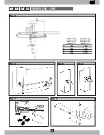
4.2 - PREPARATION FOR FIXING THE POSTERIOR CONNECTIONS
The fixing of the rear connections can be performed in either of two ways; this choice will depend on the material of the gatepost:
• if the post is in iron, the connection must be welded as shown in Figure 5;
• if the post is cement, the connection must be screwed in with plugs and screws as shown in Fig. 6.
Once the connection has been fixed, check the longitudinal and transverse alignment of the fixture with a spirit level as indicated in
Figure 8.
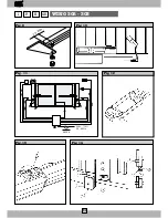
4.3 - PREPARATION FOR FIXING THE FRONT CONNECTIONS
The fixing of the front connection is performed in the following way:
• Release the WING mechanical piston as explained in paragraph 4.5 (opening the gate when there is no electricity);
• Mount the attachment stile on the WING piston pivot as shown in Figure 9;
• Bring the pivot as far forwards as possible, then back approximately 10 mm;
• Use a grinder to clean any paint from the area where you are going to weld the attachment stile;
• Use a spirit level to check the piston, and when it is perfectly level, weld two spots as shown in Figure 10;
• Remove the WING piston from the front stile, and weld the stile properly.
WARNING:
Verify the sturdiness of the piece to which the connecting pivot is welded and, if necessary, weld an adequately sized reinforce-
ment.While spot-welding the connecting pivot, always protect the rod with a cloth. A splash of molten metal can irreversibly
damage the rod and make the WING electromechanical piston useless.
• When you have welded the stile, insert the piston manoeuvring pivot into the hole in the stile, and lock it with a washer and nut;
• Put the piston back in automatic mode as described in paragraph 4.5 (opening the gate when there is no electricity).
4.4 - ELECTRICAL CONNECTIONS
When making electrical connections, be sure to follow the instructions enclosed with each of the appliances you are going to connect to
the automation system. Follow the layout of Figure 11.
When you have made the electrical connections, check the piston force, and regulate it using the electronic regulating appliances (see
the instructions supplied with each appliance).
Near the rear WING piston stile is an 8 mF capacitor (Fig. 12). To reach the capacitor, loosen the fixing screws and remove the piston
casing.
WARNING!
You MUST install electronic appliances with electrical or electronic force regulation.
4.5 - OPENING THE GATE WHEN THERE IS NO ELECTRICITY
All models come with a special key which lets you open the gate when there is no electricity. To reach the piston-locking device, turn the
protective cap, insert the key, and turn it 90° clockwise (Fig.13).
To return the gate to automatic mode, repeat the above operation while turning the key in the opposite direction.
4.6 - ELECTRIC LOCK ASSEMBLY
(Fig. 14)
1
Electric lock
2
Base of electric lock
3
Locking bolt anchor
4
Base of locking bolt anchor
5
Looking bolt
6
Peep hole (optional)
7
Gate
4.7 - GUARANTEE CONDITIONS
Our products have a 12-month guarantee running from the date of installation. Guarantee is limited only to free repairs or replacements of the
items found to be defective. Guarantee is not valid if the products have been tampered with, changed, wrongly installed or have no identification
label carrying the production code and date. We decline all responsibility for damages which, directly or indirectly, may result to people, things,
and animals when the instruction manual has not been followed. This is especially the case in respect of installation, use, and safety instruc-
tions, and when safety laws and standards in force in the country where the installation is to be carried out have not been observed.
Содержание WING 302 Series
Страница 22: ...22 ...
Страница 24: ...DEA SYSTEM s r l via Monte Summano 45E 36010 ZANÈ VI Italy ...
Страница 25: ...25 Data Tipo Intervento Tecnico ...
Страница 27: ...27 NOTE ...
Страница 28: ...28 F E GB WING 302 303 I Fig 1 Fig 2 ...
Страница 30: ...30 F E GB WING 302 303 I 6 A 220 V 10 50 60 Hz 0 030 A Fig 11 Fig 10 Fig 14 Fig 12 10 mm Fig 9 Fig 13 ...
Страница 32: ...DEA SYSTEM s r l via Monte Summano 45E 36010 ZANÈ VI Italy Tel 0445 314944 Fax 0445 314334 ß3 ...


