background image

- 1 -

© 2019 Digital Control Incorporated,
All rights reserved. 402-2049-00-A-English

digital-control.com

F

a

lc

o

n

®

Q

u

ic

k

S

ta

rt

G

u

id

e

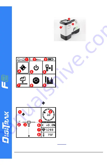
Power On the Locator

1. IR port

2. Toggle
3. Trigger

1.

Install the battery pack
and hold the trigger for
one second.

2.

Ensure the region
number in the globe
icons on the startup
screen and transmitter
match.

3.

Click the trigger twice to open the Main menu (or toggle down
at the Locate Mode screen).

Main Menu

1. Telemetry channel

2. Transmitter (Tx) band up/down
3. Locator battery status
4. Locate Mode
5. Power off
6. Calibration
7. Height-Above-Ground (HAG)
8. Settings
9. Transmitter/Frequency

Optimization (FO)

Toggle to menu options, and then click the trigger to select.

Locate Mode Screen

Select

Locate Mode

from the Main menu to start locating.

1. Locate point (ball)

2. Yaw
3. Locator with Locate Line (LL)
4. Roll indicator and value
5. Roll/pitch update meter
6. Transmitter pitch
7. Transmitter signal strength
8. Transmitter temperature

Transmitter and locator must be

paired

before data will display.

For DigiTrak remote displays, see the

DCI DigiGuide ™ App

.

Содержание DigiTrak Falcon F2

Страница 1: ...Telemetry channel 2 Transmitter Tx band up down 3 Locator battery status 4 Locate Mode 5 Power off 6 Calibration 7 Height Above Ground HAG 8 Settings 9 Transmitter Frequency Optimization FO Toggle to...

Страница 2: ...number 4 Maximum noise level 5 Up band 6 Down band 7 Scan rescan 8 Pair 9 Exit Frequency Optimization Results Run the FO for each new project to select an optimal set of frequencies for each band ever...

Страница 3: ...oth will pair at the same time and the locator will be set to use the Down band first a Install transmitter Tx batteries and endcap the increase in FO noise readings shows the Tx is on b Select Pair t...

Страница 4: ...within 5 Access AGR directly on the Calibration menu Calibrate and check AGR for both new bands If you selected two bands repeat steps 5 6 Calibration and AGR for the second band An error symbol will...

Страница 5: ...Tx changes bands data disappears from the locator Below Ground Mid Bore 10 2 7 Roll Method Disable Roll Offset if enabled 1 Roll clock wise to approx 10 o clock 1 CP Wait 10 18 seconds 2 Roll clock wi...

Страница 6: ...under the roll clock is full Always take three MAX Mode readings all three must be consistent See the DCI DigiGuide App for important information on this feature Signal Attenuation Signal attenuation...

Страница 7: ...at the LL on the line connecting the FLP and the RLP 5 Holding the trigger longer than five seconds enables MAX Mode see page 6 MAX Mode does not have to be at LL or FLP Transmitter Signal Field Geom...

Страница 8: ...view 3 Line in the Box at LL 4 HAG on 5 MAX Mode timer 6 MAX Mode icon 7 Tx depth Depth Screen Trigger held at FLP 1 Reference indicator 2 Ball in the Box 3 Roll pitch update meter 4 Tx predicted dept...

Отзывы: