ROIP302 Series User menu
3.1
Theory of Operation
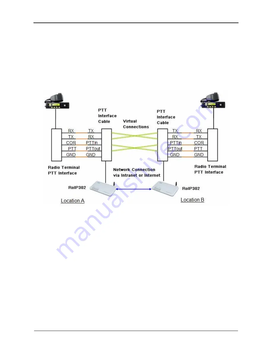
The diagram below shows the concept of how RoIP bridge the voice communication two radio
terminals at two different locations. The PTT Interface Cable provided is used to connect
between the RoIP and the radio terminal. Please note how the signals are passing between these
two devices. The connection between the two RoIP302s is through internet or intranet. The
green lines actually show how the audio and the PTT control signals are transmitted between the
two radio terminals. The two RoIPs have created a virtual connection between the two radio
terminals.
3.2
Modes of Operation
With different options, RoIPs support both Point-to-Point Mode and Group Transmit Mode
operations. Please refer to Section 3.4 for more RoIP versions available.
There are two types of RoIPs: RoIP302 and RoIP302M. RoIP302s cannot only support
Point-to-Point operation. RoIP302M has a built-in SIP server for 12 clients (RoIP302 can only
support one client) and group transmit capability. The additional feature in RoIP302M is the
built-in SIP server and the ability to transmit voice signal a maximum of 12 SIP Clients
simultaneously.
1. Point-to-Point Mode
In this mode, one RoIP302 is using public IP and the others could use public IPs of private
IPs with DDNS enabled. If the built-in SIP server is used, either one of the RoIPs can be a
www.dbltek.com


