Raider-Classic 150 (Oil-cooled&Internal Gearbox): Service Manual (single/ double-seat) EEC Version;3.0 Feb..2005
66
4.5 Regulator –Rectifier
4.5.1 Inspection of Main Wiring-Sub Electric Circuit Condition
a) Remove the 4-core connector of the regulate rectifier.
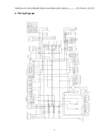
b) Measure the conducting status between the main wiring terminals according to the previous
wiring diagram.
Connecting Type
Normal Condition
Battery (The Red Wire) –Vehicle Body
Battery Voltage Value
Connecting Wire (the Green Wire) –Vehicle Body
Conductive
Lighting Wire (the Yellow Wire)—Vehicle Body (Remove the
resistor, side auto-starter plug, and turn the lighting switch to off)
Generally : 0.1-0.8
Ω
Charging Wire (the White Wire)—Vehicle Body
Generally: 0.2-2.0
Ω
W (White)
Y (Yellow)
R (Red)
G (Green)
W (White)
∞
3 - 100 K
Ω
∞
Y (Yellow)
∞
∞
5 - 100 K
Ω
R (Red)
∞
∞
∞
Take the voltage regulate rectifier inspection procedure by two steps:
First inspect the main wiring—sub electric circuit condition, and then inspect the
voltage regulator.
Inspect only when the engine is cold.


