


INSTALLATION INSTRUCTIONS
R
−
410A Split System Heat Pumps
6
428 01 1703 01
Specifications subject to change without notice.
4. Close nitrogen valve and allow system to stand for 1
hour. During this time, dry nitrogen will diffuse
throughout the system absorbing moisture.
5. Repeat this procedure as indicated in Figure 6.
6. After the final evacuate sequence, confirm there are no
leaks in the system. If a leak is found, repeat the entire
process after repair is made.
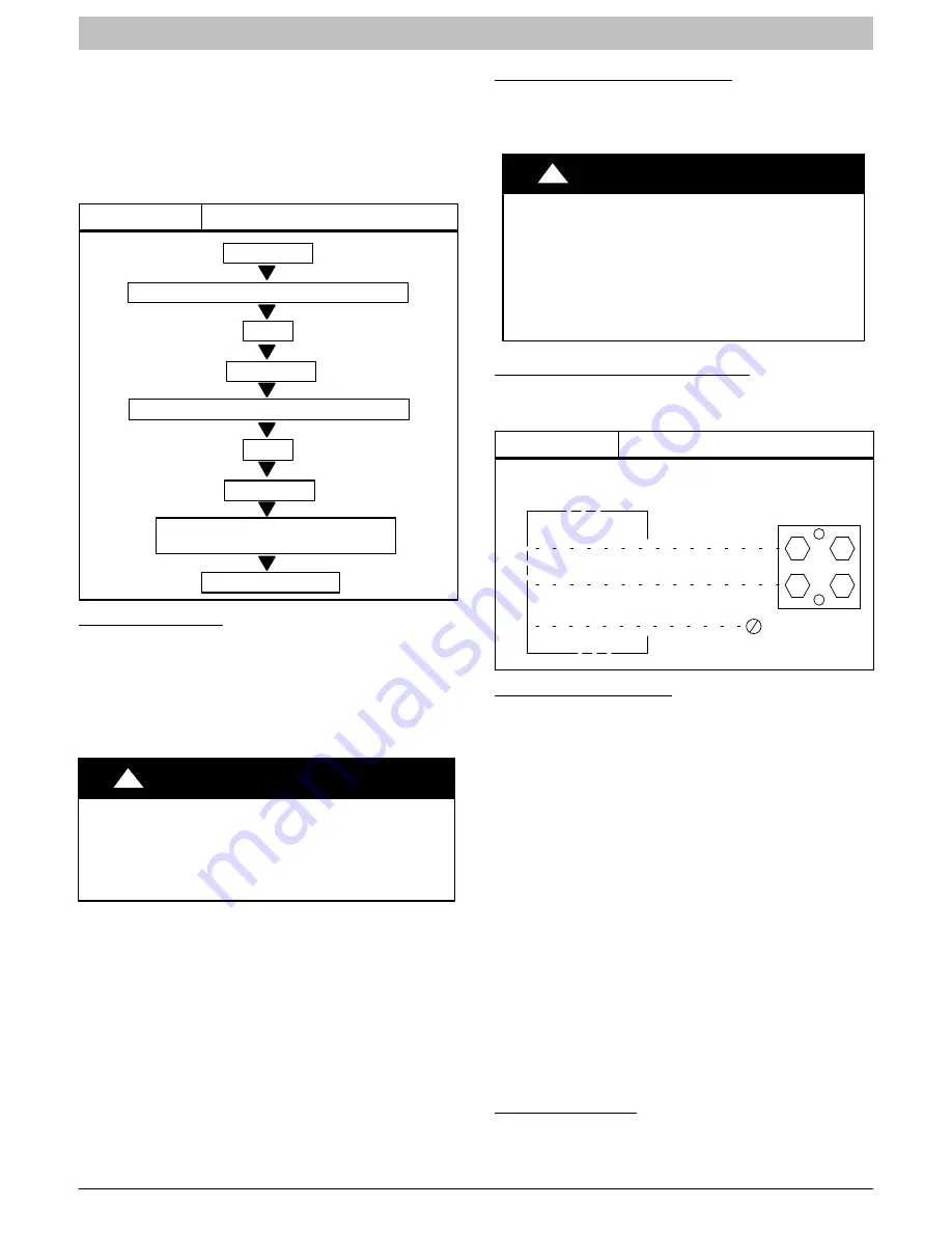
Figure 6
Triple Evacuation Sequence
EVACUATE
BREAK VACUUM WITH DRY NITROGEN
WAIT
EVACUATE
CHECK FOR TIGHT, DRY SYSTEM
(IF IT HOLDS DEEP VACUUM
CHARGE SYSTEM
BREAK VACUUM WITH DRY NITROGEN
WAIT
EVACUATE
Final Tubing Check
IMPORTANT
: Check to be certain factory tubing on both
indoor and outdoor unit has not shifted during shipment.
Ensure tubes are not rubbing against each other or any
sheet metal. Pay close attention to feeder tubes, making sure
wire ties on feeder tubes are secure and tight.
Make Electrical Connections
!
WARNING
ELECTRICAL SHOCK HAZARD
Failure to follow this warning could result in personal
injury or death.
Do not supply power to unit with compressor terminal box
cover removed.
Be sure field wiring complies with local and national fire,
safety, and electrical codes, and voltage to system is within
limits shown on unit rating plate. Contact local power
company for correction of improper voltage. See unit rating
plate for recommended circuit protection device.
NOTE
: Operation of unit on improper line voltage constitutes
abuse and could affect unit reliability. See unit rating plate.
Do not install unit in system where voltage may fluctuate
above or below permissible limits.
NOTE
: Use copper wire only between disconnect switch and
unit.
NOTE
: Install branch circuit disconnect of adequate size per
NEC to handle unit starting current. Locate disconnect within
sight from and readily accessible from unit, per Section
440
−
14 of NEC.
Route Ground and Power Wires
Remove access panel to gain access to unit wiring. Extend
wires from disconnect through power wiring hole provided
and into unit control box.
!
WARNING
ELECTRICAL SHOCK HAZARD
Failure to follow this warning could result in personal
injury or death.
The unit cabinet must have an uninterrupted or
unbroken ground to minimize personal injury if an
electrical fault should occur. The ground may consist
of electrical wire or metal conduit when installed in
accordance with existing electrical codes.
Connect Ground and Power Wires
Connect ground wire to ground connection in control box for
safety. Connect power wiring to contactor as shown in Fig. 7.
Figure 7
Line Power Connections
DISCONNECT
PER N. E. C. AND/OR
LOCAL CODES
CONTACTOR
GROUND
LUG
FIELD GROUND
WIRING
FIELD POWER
WIRING
Connect Control Wiring
This unit is capable of communication with an Observer Wall
Control, or will operate using standard 24v 2
−
stage
thermostat. Route 24v control wires through control wiring
grommet and connect leads to control board. When an
Observer Wall Control is available, connect DX+ and DX
−
connections only. If additional grounding is needed use C
terminal. If a 2
−
stage thermostat is used, connect to the Y1,
Y2, W1, O, and C connections. Refer to the wiring label for
further clarification.
Use No. 18 AWG color
−
coded, insulated (35
C minimum)
wire. If thermostat is located more than 100 ft. (30.48 m)
from unit, as measured along the control voltage wires, use
No. 16 AWG color
−
coded, insulated wire to avoid excessive
voltage drop.
All wiring must be NEC Class 1 and must be separated from
incoming power leads.
Use furnace transformer, fan coil transformer, or accessory
transformer for control power, 24
−
v/40
−
va minimum.
NOTE
: Use of available 24
−
v accessories may exceed the
minimum 40
−
va power requirement. Determine total
transformer load and increase the transformer capacity or
split the load with an accessory transformer as required.
Final Wiring Check
IMPORTANT
: Check factory wiring and field wire connections
to ensure terminations are secured properly. Check wire
routing to ensure wires are not in contact with tubing, sheet
metal, etc.


