


Page 6
Wireless Temperature/Humidity Station
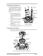
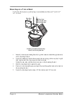
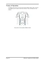
2.
Install the Junction Board Cover as shown in the illustration. The Junction Board
Cover presses easily into place when you are installing it.
Note:
To remove the cover, press gently in on both sides to release the latches holding it in
place.
3.
Place the two radiation shield plates on top of the fan plate, open plate first with the
closed plate on top, being careful to line up the three screw holes.
4.
Gently place the mounting bracket on top of the radiation shield, being careful to
line up the three screw holes and also being very careful not to move the top two
(2) radiation shield plates.
5.
Fasten the mounting plate securely to the radiation shield using three (3) long
screws.
Tip:
Hold the mounting bracket in place with one hand while you start the three (3)
long screws.Be sure to start all three screws before you tighten any of them.
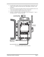
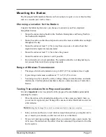
Preparing the SIM for Installation
The Temp/Hum sensors are connected by a cable to the
Sensor Interface Module
(SIM), located inside the SIM housing. The SIM contains electronics that measure and
store the temperature and humidity values for transmission to the console via cable or
radio. The SIM housing protects the SIM from the elements and provides easy access to
SIM cable connections.
Connecting the Sensors
1.
Take one of the square rubber grommets from the bottom of the SIM housing and
run the cables for the UV and Solar Radiation sensors through it, if included on
your station.
2.
Run the Solar Power cable through the grommet.
3.
Take the other square rubber gromment and run Temp/Hum sensor cable through it.
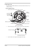
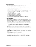
Junction Board
Cover
Junction
Board
Press in on Sides
near latches to
install or remove
cover.
Note:
Junction Board Cover Installation


