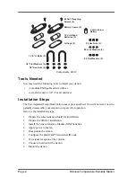
Davis Instruments Fan-Aspirated Radiation Shield Скачать руководство пользователя страница 10

Page 10

Wireless Temperature/Humidity Station
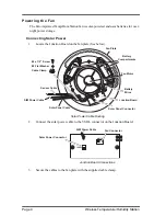
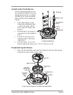
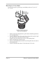
5.

Set the switch to the ON position using a ball-point pen or paper clip. When in test 
mode, an LED indicator light flashes each time the station transmits: 

• The LED will immediately flash once to show that the light itself functions.

• Then it will flash each time the transmitter broadcasts a signal, which 

should be every 10 seconds. 

6.

If the LED flashes only once and then remains dark, there is a problem with the 
transmitter. Refer to Troubleshooting on page 17.

7.

If the LED flashes repeatedly but your console isn’t picking up a signal anywhere 
in the room, it could be related to one of the following causes: 

• The ID switches were not correctly set on the transmitter. 

• Review the procedure on page 8. 

• The station ID was not correctly set on the console/receiver. 

• Review the procedure on page 9. 

• Reception is being disrupted by RF (radio frequency) interference.

• There is a problem with the console/receiver. 

• Refer to Troubleshooting, page 17.
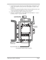
Note:

Remember 

to set the Test switch

 OFF when you’re finished testing wireless trans-

mission. If it is left ON, the blinking LED will significantly reduce battery life.

Содержание Fan-Aspirated Radiation Shield

Страница 1: ...ombines fan aspiration and passive shielding to minimize the effects of solar radiation on temperature measurement This manual pro vides step by step instructions for installing your Fan Aspirated Tem...

Страница 2: ...tallation steps 1 Prepare the solar radiation shield for installation 2 Prepare the SIM for installation 3 Install the Sensor Interface Module SIM batteries 4 Apply power to the fan 5 Reassemble the s...

Страница 3: ...ting the mounting bracket to the radiation shield 2 Lift the mounting bracket off of the radiation shield 3 Remove the top two 2 radiation shield plates to expose the fan plate and junction board 2 Sc...

Страница 4: ...ow 2 Connect the solar power cable to the VSOL connector on the Junction Board 3 Secure the cables to the fan plate with the supplied cable clamp Fan Plate Junction Board Battery Wires Sensor Cable So...

Страница 5: ...ir up and away from the Temp Hum sensor 3 Insert the O ring in the groove around the edge of each battery compartment 4 Attach the battery covers to the battery compartments using two 4 x 3 8 9 5 mm s...

Страница 6: ...th one hand while you start the three 3 long screws Be sure to start all three screws before you tighten any of them Preparing the SIM for Installation The Temp Hum sensors are connected by a cable to...

Страница 7: ...lustration below and connect the temperature humidity sensor cable as shown below 6 Connect the Solar Power Cable to the SIM as shown below 7 Insert the 3 volt lithium battery into the battery holder...

Страница 8: ...e that means the transmitter ID switches are in the OFF position when each transmitting station leaves the factory Your Fan Aspirated Temp Hum Station requires a different DavisTalk transmitter ID tha...

Страница 9: ...you chose for your station use the UP or DOWN arrow keys to set the reception of that ID code to ON 4 Press the GRAPH key to change the station assigned to that transmitter ID to TEMP HUM 5 To exit S...

Страница 10: ...fer to Troubleshooting on page 17 7 If the LED flashes repeatedly but your console isn t picking up a signal anywhere in the room it could be related to one of the following causes The ID switches wer...

Страница 11: ...e of Wireless Transmission The range of wireless transmission is up to 400 125 m outdoors line of sight Typical range under most conditions is 75 to 150 23 to 46 m Your range may be reduced by walls c...

Страница 12: ...mounting bracket using a 8 flat washer 8 split lock washer and 8 hex nut one each of the stud ends Tighten the hex nuts until the station is secure on the mounting bracket 3 Hold the mounting bracket...

Страница 13: ...tation Put two U bolts around the pole and insert the ends through the holes in the back of the mounting bracket 8 Secure the SIM housing using 1 4 flat washers and 1 4 hex nuts 1 4 Flat Washers 1 1 2...

Страница 14: ...Drill holes using a 3 16 5 mm drill bit Use a carpenter s level when marking the holes to ensure that the bracket will be level Attaching Mounting Bracket to a Post 2 Slide the stud ends protruding f...

Страница 15: ...t using a 8 flat washer 8 split lock washer and 8 hex nut on each of the stud ends Tighten the hex nuts until the station is secure on the mounting bracket 8 Hex Nuts 8 Lock Washers 8 Flat Washers 1 4...

Страница 16: ...aspiration and no nighttime aspiration Wireless Repeater A wireless repeater 7624 or 7625 can be used to extend the range of wireless trans mission between the station and the Vantage Pro console Mai...

Страница 17: ...you are experiencing problems with your Fan Aspirated Temp Hum Station first be sure to check all cable connections If you are unable to solve the problem please call Davis Technical Support We ll be...

Страница 18: ...ion Theory of Operation The diagram below shows how the Fan Aspirated Temp Hum Station draws outside air up through the sensor chamber and between the three walls surrounding the sensor chamber Cross...

Страница 19: ...up power Optional Vantage Pro AC power adapter Fan Aspirated Radiation Shield Aspiration Rate Full Sun 190 feet min 96 m s Aspiration Rate Batteries Only 80 feet min 9 4 m s Radiation Induced Temperat...

Страница 20: ...generates uses and can radiate radio frequency energy and if not installed and used in accordance with the instructions may cause harmful interference to radio communications However there is no guar...

Отзывы: