background image


Page 10

EZ-Mount Advanced Station


Mounting the Sensor Array


The sensor array has been pre-assembled for easy installation. However, you 
will still need to provide a solid mounting for the sensor array. Mounting hard-
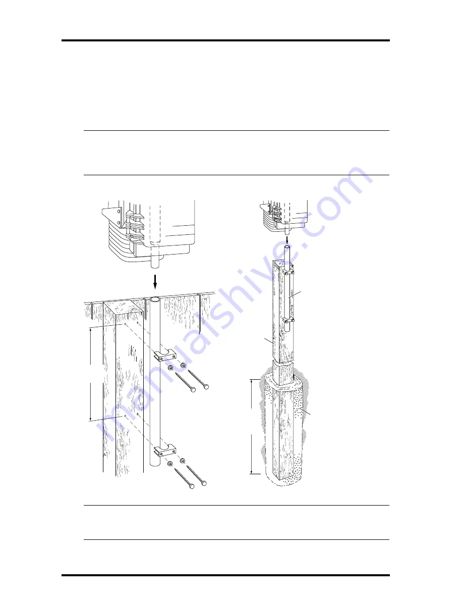
ware has been included for the most common installations (see figures below). 
If you are using the optional Mounting Tripod, consult the tripod’s manual for 
mounting instructions. 


CAUTION:


The station’s wind direction is calibrated as if the horizontal part of the anemometer arm 

were pointing west. If you plan to mount the station facing a different direction, see “Recali-
brating the Wind Vane” on page 12 for instructions on how to adjust the wind vane accord-


ingly. 


Note:


For roof mounting, we recommend the optional Mounting Tripod. If mounting on a roof, tower, or 
other elevated structure without the Tripod, be sure to consider the effects of lightning, wind 


loading and vibration and design the installation accordingly. 

Support Tube
(swaged end)

Extension Tube
(21" long, no swaged end)

1-1/8" Saddle

5/16" Flat Washer

5/16" x 3" Lag Screw

12"

minimum

2' of

post

buried

Extension Tube
(see fence mounting for details)

4 x 4
treated
post, 
8' long

Use post hole
digger, fill hole
with post hole
concrete

MOUNTING ON A FENCE

MOUNTING ON A POST

Sensor Array

Sensor Array

Содержание Energy EnviroMonitor

Страница 1: ...dard and industrial The industrial option offers greater protection from radio frequency interference electrostatic discharges and voltage surges by provid ing 100 feet of shielded cable an extra grou...

Страница 2: ...ctor Cone EZ Sensor Arm Additional Components for INDUSTRIAL Installations Only ICAM Kit 8 Conductor Cable Standard for ICAM to Console 25 7 5m 16 5 5m Ground Wire 6x1 25mm Screws Cable Ties Adhesive...

Страница 3: ...the extension tube page 4 Attach the anemometer page 4 Attach the wind cups page 4 Snip the cable tie in the rain collector page 5 Apply power to the console page 5 Attach the EZ Sensor Arm page 6 Con...

Страница 4: ...s positioned over the white field case and NOT over the black rain collec tor cone 3 Attach the wind cups to the anemometer Push the wind cups onto the shaft as far as they will go then tighten the se...

Страница 5: ...rge tab between the two oblong holes on the base s underside and pulling the base free Plug the power adapter into the center Power slot as shown below and then plug the other end into a 110 VAC outle...

Страница 6: ...port tube insert the EZ Sensor Arm letting the wire drop through the bottom gap in the brace clamp and tighten Alternative EZ Sensor Arm Positioning You may face the sensors straight up as shown above...

Страница 7: ...ere Note This alternative configuration is not standard for meteorological measurements Use the following rubric to determine the tilt angle for maximum readings Maximum Readings During Spring or Fall...

Страница 8: ...d release the lever d Connect the bare drain wire to the SHIELD terminal JP2 and cut off any excess drain wire e Attach the ground wire to the SHIELD terminal JP2 as well Run the ground wire and the s...

Страница 9: ...in the sensor array field case keeping in mind that you will need a power source you should locate the console indoors For more accurate readings follow these suggestions Avoid placing console in dir...

Страница 10: ...the station facing a different direction see Recali brating the Wind Vane on page 12 for instructions on how to adjust the wind vane accord ingly Note For roof mounting we recommend the optional Mount...

Страница 11: ...ble underneath the eaves of your house or in another location similarly shielded from rain place cable clips or weather resistant cable ties approximately every 3 5 feet 1 1 6 m Note Do not use metal...

Страница 12: ...compass or local area map to determine which direction N S E W NE etc the anemometer arm is pointing 4 Use the wind direction chart to find the degree reading which corresponds to that direction 5 Sl...

Страница 13: ...ON A SHELF Or to display the console on a wall follow these steps a Hold the mounting base flat against the wall and use a pencil to mark the location of the two keyholes b Use an electric drill with...

Страница 14: ...AC DC power cord and listen for 2 beeps within 10 seconds Note If you have the WeatherLink installed listen for 3 beeps within 20 seconds and then if all is well try communicating with the WeatherLink...

Страница 15: ...ly with the limits for a Class B digital device pursuant to Part 15 of the FCC Rules These limits are designed to provide reasonable protection against harmful interference in a residential installati...

Страница 16: ...iroMonitor and Health EnviroMonitor Systems Rev A Manual 7 8 99 Controlled online Weather Manuals Consoles EZ EZ Adv This product complies with the essential protection requirements of the EC EMC Dire...

Отзывы: