8
Drawing 1-C VM10
1a. Coupling guard-left
1b. Coupling guard-right
2. Screw, washer
3. Pump head
3a. Lining
4. Diffuser
4a. Support diffuser
4b. Neck ring cover
4c.Neck ring
5. Coupling
5a. Inducer
6. Baseplate
7. Shaft pin
8. Nut M16
8a. Washer 16
9. Screw
10. Circlip cover
14. Strap
17. Impeller sleeve 29X17.4
20. Flange
21. Retaining ring
22. Supporting washer
23. Nut M10-LH
24. Impeller washer
25. Staybolt
26a. lnlet&outlet chamber-Flange type
26d. lnlet&outlet chamber-pipe thread type
28. Drain screw
29. Drain plug
30. O-ring 15X3. 3
31. Y ring
33. Sleeve for support diffuser
34. Mechanical seal
36. Air vent plug
37. O-ring 16X2.8
38. Air vent screw
39. Bolt, washer
40. Motor
46. Adjusting rubber
47a. Bearing
49. Impeller
50a. Top diffuser
51. Shaft
55. Cylinder
60. Corrugated spring
63. O-ring retainer
65. Screw M8X20
Содержание VM Series
Страница 19: ...19 2 See drawing 5 B for assembling order of VM5 Symbol information Drawing 5 B VM5 assembling order...
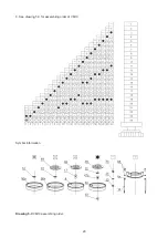
Страница 20: ...20 3 See drawing 5 C for assembling order of VM10 Symbol information Drawing 5 C VM10 assembling order...
Страница 21: ...21 4 See drawing 5 D for assembling order of VM15 20 Symbol information Drawing 5 D VM15 20 assembling order...
Страница 22: ...22 5 See drawing 5 E for assembling order of VM32 Symbol information Drawing 5 E VM32 assembling order...
Страница 23: ...23 6 See drawing 5 F for assembling order of VM42 Symbol information Drawing 5 F VM42 assembling order...
Страница 24: ...24 7 See drawing 5 G for assembling order of VM65 Symbol information Drawing 5 G VM65 assembling order...
Страница 25: ...25 8 See drawing 5 H for assembling order of VM90 Symbol information Drawing 5 H VM90 assembling order...
Страница 27: ...27 NOTES...


