26
8. FAULT FINDING
Before removing the terminal box cover, make sure that the power supply has been
switched off.
Fault
Cause
Solution
Motor does not run
when started.
a) Power supply failure.
b) Fuses are blown.
c) Motor overloaded.
d) Motor starter failure.
e) Control circuit is defective.
f) Motor is defective.
a) Check power supply.
b) Replace fuses.
c) Check pump system.
d) Replace starter.
e) Replace control circuit.
f) Repair motor.
g) Check capacitors on single phase
models.
Motor-protective
circuit breaker trips
out immediately when
supply is switched on.
a) Fuses are blown.
b) Contacts in motor-protective circuit
breaker are faulty.
c) Cable connection is loose or faulty.
d) Motor winding is defective.
e) Pump mechanically blocked.
f) Motor-protective circuit breaker setting
is too low.
g) Start / run capacitors are faulty.
a) Replace fuses.
b) Check or replace starter.
c) Check cables or power supply.
d) Replace motor.
e) Check amd clean impurities.
f) Reset motor-protective circuit
breaker.
g) Check capacitors on single phase
models.
h) Refer to VFD control manual.
i) Replace start/run capacitors.
Motor-protective
circuit breaker trips
out occasionally.
a) Motor-protective circuit breaker
setting is too low.
b) Power supply failed periodically.
c) Low voltage at peak times.
a) Set the motor-protective
circuit breaker correctly.
b) Check power supply.
c) Add voltage stable device
Motor-protective
circuit breaker has
not tripped out but the
pump does not run
a) Contacts in motor-protective circuit
breaker are faulty.
b) Control circuit is defective.
a) Check or replace motor
protective circuit breaker.
b) Replace control circuit.
Pump performance
not constant.
a) Pump inlet pressure is too low
(cavitation).
b) Suction pipe/pump partly blocked
by impurities.
c) Pump draws in air.
d) Pump runs in the wrong direction
of rotation.
a) Check the suction conditions.
b) Clean the suction pipe/pump.
c) Check the suction conditions.
d) Change the motor running
direction.
e) Bleed air from system.
Pump runs but gives
no water.
a) Suction pipe/pump blocked by impurities.
b) Foot or non-return valve blocked in
closed position.
c) Leakage in suction pipe.
d) Air in suction pipe or pump.
a) Clean the suction pipe/pump.
b) Repair the foot or non-return
valve.
c) Repair the suction pipe.
d) Re-priming, vent air.
Abnormal vibration
or noise.
a) Leakage in suction pipe.
b) Suction pipe is too small or partly
blocked by impurities.
c) Air in suction pipe or pump.
d) Pump mechanically blocked.
e) Motor bearing failure.
f) Stack height incorrect
a) Repair the suction pipe.
b) lnstall larger suction pipe or
clean the suction pipe.
c) Re-priming, vent air.
d) Repair pump.
e) Replace motor bearing.
f) Adjust stack height
Leakage in
mechanical seal.
a) Mechanical seal is defective.
a) Replace the mechanical seal.
Содержание VM Series
Страница 19: ...19 2 See drawing 5 B for assembling order of VM5 Symbol information Drawing 5 B VM5 assembling order...
Страница 20: ...20 3 See drawing 5 C for assembling order of VM10 Symbol information Drawing 5 C VM10 assembling order...
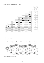
Страница 21: ...21 4 See drawing 5 D for assembling order of VM15 20 Symbol information Drawing 5 D VM15 20 assembling order...
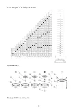
Страница 22: ...22 5 See drawing 5 E for assembling order of VM32 Symbol information Drawing 5 E VM32 assembling order...
Страница 23: ...23 6 See drawing 5 F for assembling order of VM42 Symbol information Drawing 5 F VM42 assembling order...
Страница 24: ...24 7 See drawing 5 G for assembling order of VM65 Symbol information Drawing 5 G VM65 assembling order...
Страница 25: ...25 8 See drawing 5 H for assembling order of VM90 Symbol information Drawing 5 H VM90 assembling order...
Страница 27: ...27 NOTES...


