DN200 User Manual Rel 1.0
•
Avoid any partial line of sight between the antennas
•
Be cautious of trees or other foliage that may be near the path, or may grow and obstruct the
path
•
Be sure there is enough clearance from buildings and that no building construction may
eventually block the path
•
Check the topology of the land between the antennas using topographical maps, aerial
photos, or even satellite image data (software packages are available that may include this
information for your area)
1.2
Antenna Height
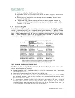
A reliable wireless link is usually best achieved by mounting the antennas at each end, high enough for a
clear radio line of sight between them. The minimum height required depends on the distance of the link,
obstacles that may be in the path, topology of the terrain, and the curvature of the earth (for links over 3
miles). For long-distance links, the AP may have to be mounted on masts or poles that are tall enough to
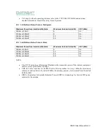
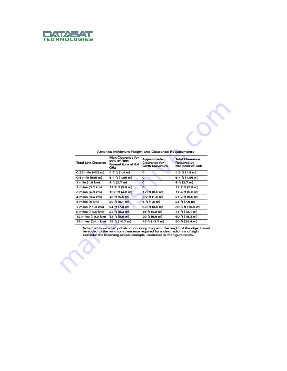
attain the minimum required clearance. Use the following table to estimate the required minimum
clearance above the ground or path obstruction (for 5 GHz links).
1.2.1 Antenna Position and Polarization
Once the required antenna height has been determined, other factors affecting the precise position of the
wireless Access Point must be considered:
•
Be sure there are no other radio antennas within 2 m (6 ft) of the wireless access point. These include
other Wi-Fi radio antennas
•
Place the wireless access point away from power and telephone lines
•
Avoid placing the wireless device too close to any metallic reflective surfaces, such as roof-installed
air-conditioning equipment, tinted windows, wire fences, or water pipes. Ensure that there is at least 5
feet clearance from such objects
•
The wireless device antennas at both ends of the link must be positioned with the same polarization
direction, either horizontal, vertical or diagonal slant. Proper alignment helps to maximize
throughput. Ensure, the antennas are aligned to the main lobes and not mis-aligned to side lobes. The
link will give reduced SNR (Signal to Noise Ratio) and be unstable.
Содержание DN200
Страница 23: ...DN200 User Manual Rel 1 0 1 7 NAT Firewall...
Страница 27: ...DN200 User Manual Rel 1 0...
Страница 38: ...DN200 User Manual Rel 1 0...
Страница 39: ...DN200 User Manual Rel 1 0 1 19 1 Vibration Certification...

