


AP25 Installation and Operating Guide
Page 90
AP25 Installation & Operating Guide
Document # 9301H79500 Ver. 1.00
Set the crossover ID for easy identification. Here we set the crossover ID for channel 1 output
L
which identifies it as the low frequency output for channel one (1). This is only a label for easy
identification and does not affect the crossover itself.
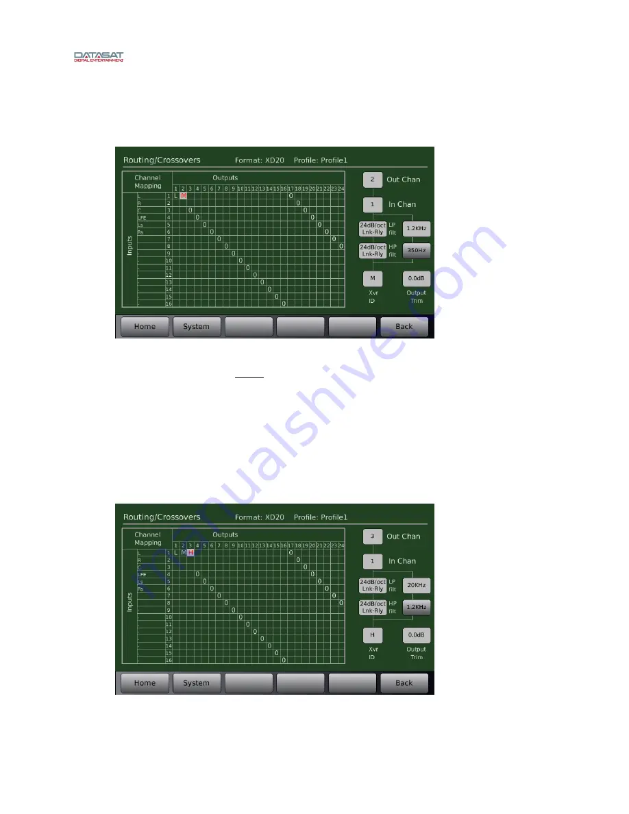
Mid Frequency
Figure 69. Example – Mid Frequency Crossover Setup
As shown in Figure 69, set output channel
2
for the mid range driver. Make sure the input
channel is still set to
1
(or left channel, remember, left = channel 1 in the example).
Set the low pass filter to the mid range driver’s upper crossover point, which in this case is
1200Hz
.
Set the high pass filter to the mid range driver’s lower crossover frequency, which in this case is
350Hz
.
Set the slope to
24dB/octave
.
Set the crossover ID to
M
to identify it as the midrange frequency output for channel two (2).
High Frequency
Figure 70. Example – High Frequency Crossover Setup
Содержание AP25
Страница 46: ...AP25 Installation and Operating Guide Page 46 AP25 Installation Operating Guide Document 9301H79500 Ver 1 00...
Страница 47: ...AP25 Installation and Operating Guide Page 47 AP25 Installation Operating Guide Document 9301H79500 Ver 1 00...
Страница 48: ...AP25 Installation and Operating Guide Page 48 AP25 Installation Operating Guide Document 9301H79500 Ver 1 00...
Страница 49: ...AP25 Installation and Operating Guide Page 49 AP25 Installation Operating Guide Document 9301H79500 Ver 1 00...
Страница 50: ...AP25 Installation and Operating Guide Page 50 AP25 Installation Operating Guide Document 9301H79500 Ver 1 00...
Страница 122: ...AP25 Installation and Operating Guide Version 1 00 Appendix B Interface Wiring Diagrams B 2 Document 9301H79500 Ver 1 00...
Страница 123: ...AP25 Installation and Operating Guide Version 1 00 Appendix B Interface Wiring Diagrams B 3 Document 9301H79500 Ver 1 00...
Страница 124: ...AP25 Installation and Operating Guide Version 1 00 Appendix B Interface Wiring Diagrams B 4 Document 9301H79500 Ver 1 00...
Страница 125: ...AP25 Installation and Operating Guide Version 1 00 Appendix B Interface Wiring Diagrams B 5 Document 9301H79500 Ver 1 00...
Страница 126: ...AP25 Installation and Operating Guide Version 1 00 Appendix B Interface Wiring Diagrams B 6 Document 9301H79500 Ver 1 00...
Страница 127: ...AP25 Installation and Operating Guide Version 1 00 Appendix B Interface Wiring Diagrams B 7 Document 9301H79500 Ver 1 00...
Страница 128: ...AP25 Installation and Operating Guide Version 1 00 Appendix B Interface Wiring Diagrams B 8 Document 9301H79500 Ver 1 00...


