background image

Cabling

14

Cabling

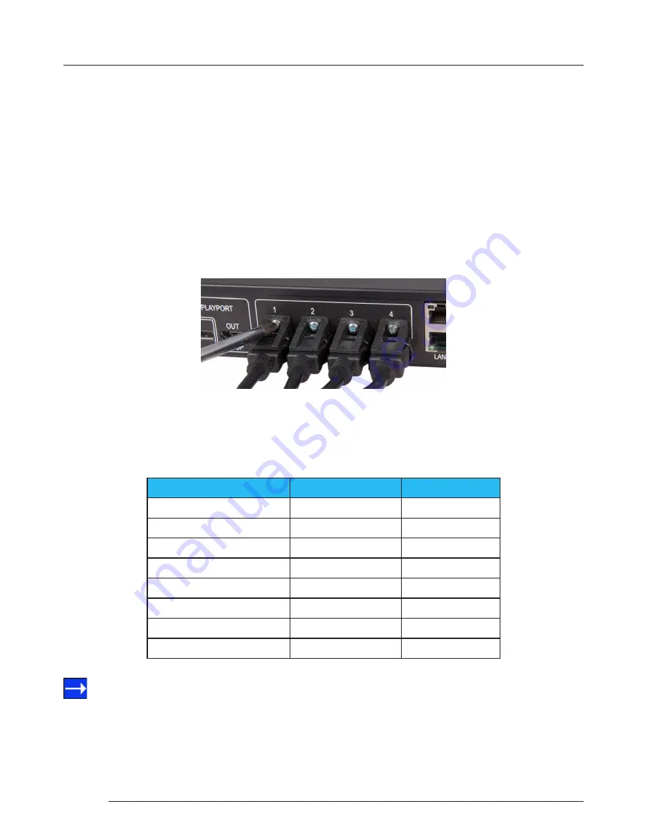
6.5  Connecting Outputs to Monitors

Each Fx4 display controller can support up to 4 monitors on a display wall, the output connectors will be HDMI or DisplayPort 
depending on the model ordered.  Once again it is highly recommended that locking cables are used.

Each output can display any region of the input image, all the required cropping, scaling and rotations is calculated within the 

Fx4 hardware.

Cable Type

Bit Rate

 Maximum Length (m)

HDMI (output)

N/A

10

DisplayPort (output)

Reduced  Bit Rate (RBR)

20

DisplayPort (output)

High Bit Rate (HBR)

10

DisplayPort (Loop through)

Reduced  Bit Rate (RBR)

20

DisplayPort (Loop through)

High Bit Rate (HBR)

10

DisplayPort (Loop through)

High Bit Rate 2 (HBR2)

2

Ethernet Cable (Network/Setup)

N/A

100

USB (Setup)

N/A

3

6.4  Connecting the Out Loop

The Out Loop connector is used to connect two or more Fx4’s when the requirement is to create large video display walls with 

more than 4 monitors.

 Using a DisplayPort cable (not supplied) connect the Out Loop from the first Fx4 to the DisplayPort Input on the second Fx4  
and so on until all the required units are connected.  The input signal will be gen-locked through all the connected Fx4’s in the 

chain.

6.5.1 Cable Lengths

Workable cable lengths depend on the quality of the cables used to set up your Fx4,  Datapath recommends using certified 

cables when installing your Fx4.

Connecting HDMI Output Cable

  The Wall Designer software has a Maximum Link Rate selector which enables you to manually select the link rate of the 

DisplayPort input to suit your own requirements. The default rate of HBR2 allows operation up to the full 4k/60 capability of the 
DisplayPort input, but if the actual input signal is only HD then the maximum link rate can be changed to HBR or RBR to enable 

the use of longer cables.

Содержание Fx4

Страница 1: ...Multi Display Controller USER GUIDE Version 1 0 0...

Страница 2: ...Panel 8 4 2 Rear Panel 8 4 3 Rack Mounting the Fx4 9 Chapter 5 Software 10 5 1 Wall Designer 10 5 2 Wall Designer Features 10 5 4 Running theWall Designer Application 11 Chapter 6 Cabling 13 6 1 Conne...

Страница 3: ...9 8 2 Technical Support 19 Chapter 9 Maintenance 20 9 1 Maintenance of the Fx4 20 Chapter 10 Environmental 21 10 1 Certification and Compliances 21 Chapter 11 Specifications 22 Chapter 12 Warranty RMA...

Страница 4: ...ions and pages are numbered individually Pages are numbered in Arabic numerals with the exception of the cover page no numbering 1 3 Fonts and Symbols 1 3 1 Fonts The font used throughout the user gui...

Страница 5: ...1 4 Working Environment The equipment should be located in an environment free from dust moisture and extreme changes in temperature and should be placed on a stable and solid work surface Liquids hot...

Страница 6: ...have an adverse affect on the operation of the system or could cause injury to the operator Should there be any physical damage to the power sockets or exposed wiring do not connect to a power source...

Страница 7: ...hernet loop through is supported on the second port meaning multiple devices can be connected 3 2 Features Each output monitor can take its input from any region of the input image as all of the requi...

Страница 8: ...inated the Input LED indicates a valid source is connected Status Continuous illumination Indicates the Fx4 is operating normally Flashing Unit is operating over the normal operating temperature Ensur...

Страница 9: ...e Fx4 in a daisy chain architecture using Ethernet cables Ethernet loop through is supported The LAN connector can also be used to connect the Fx4 to a PC for configuration USB The USB socket is used...

Страница 10: ...that users regularly visit the Datapath website for information on new software releases Insert the software CD into a CD DVD drive and the installation wizard should begin automatically Should the in...

Страница 11: ...wizard will continue installing the software 5 3 3 View Readme Click onView Readme to open an HTML document containing the latest information and bug fixes for the application TheWall Designer applica...

Страница 12: ...the outputs from the devices to specific monitors on the display wall For ease of useWall Designer has an automatic configuration feature Auto config which when clicked automatically adds the require...

Страница 13: ...on non lockable HDMI cables to ensure they remain firmly attached to the Fx4 Connecting HDMI Input Cable 6 3 Connecting Input Sources The Datapath Fx4 has three dedicated input connectors 2 x HDMI an...

Страница 14: ...p connector is used to connect two or more Fx4 s when the requirement is to create large video display walls with more than 4 monitors Using a DisplayPort cable not supplied connect the Out Loop from...

Страница 15: ...DisplayPort 7 1 2 Connecting Outputs Depending on the Fx4 model ordered either HDMI or DisplayPort cables are required not supplied The Fx4 has 5 output connectors 4 x monitor outputs and 1 x DisplayP...

Страница 16: ...ices window is where the input devices and monitors are linked to complete the design of the video wall this is done by allocating inputs to devices and the outputs from the devices to specific monito...

Страница 17: ...he device by right clicking then select Associate Device from the displayed menu a list of available Fx4 s is displayed Click on the virtual device to display its properties the Device Properties can...

Страница 18: ...the IP Address Subnet Mask and Gateway can be manually configured Dual Ethernet Ports Connect the Fx4 to a network using the top LAN connector then open Wall Designer and create your display layout as...

Страница 19: ...e visual representation of the Fx4 appears in the Device window a blue information icon will be displayed Click on the information icon for details of available upgrades 8 1 4 Intermittent or Loss of...

Страница 20: ...Your Fx4 requires little maintenance however care should be taken to keep all ventilation holes clear to allow an unrestricted flow of air through the unit Note Failure to keep ventilation holes clear...

Страница 21: ...ply with the limits for a Class A digital device pursuant to part 15 of the FCC Rules These limits are designed to provide reasonable protection against harmful interference when the equipment is oper...

Страница 22: ...up to 165 MP s DisplayPort Model 4 x DisplayPort 1 1 1080p 60 or equivalent up to 165MP s Loop through both models DisplayPort1 2 locked to selected video input resolution Input Surface 8k x 8k maximu...

Страница 23: ...ew or previously repaired product and returned to you at our cost b The product is out of warranty and is found to be faulty The product if possible will be repaired or replaced at fixed cost as state...

Страница 24: ...h Limited Whilst every effort is made to ensure that the information contained in this User Guide is correct Datapath Limited make no representations or warranties with respect to the contents thereof...

Страница 25: ...ensTurn Red 19 Disposal 21 F FCC Rules 21 Features 7 Firmware Support 22 Fonts and Symbols 4 G Gateway 18 Genlock Input 22 H HDMI Cable Lock 13 Help Files 12 High Bit Rate 14 I Initial Inspection 5 6...

Страница 26: ...c IP s 18 StorageTemperature 22 Subnet Mask 18 Switching On 15 Symbols 4 Sync 8 T Toolbar 11 12 U Unpacking 5 6 Upload Logo 17 User Manual 11 V Ventilation 5 Ventilation holes 20 Video Input Connectio...

Отзывы: