background image

CiB

9224


V12


User


Manual


30


2.9  Air Duct


2.9.1 

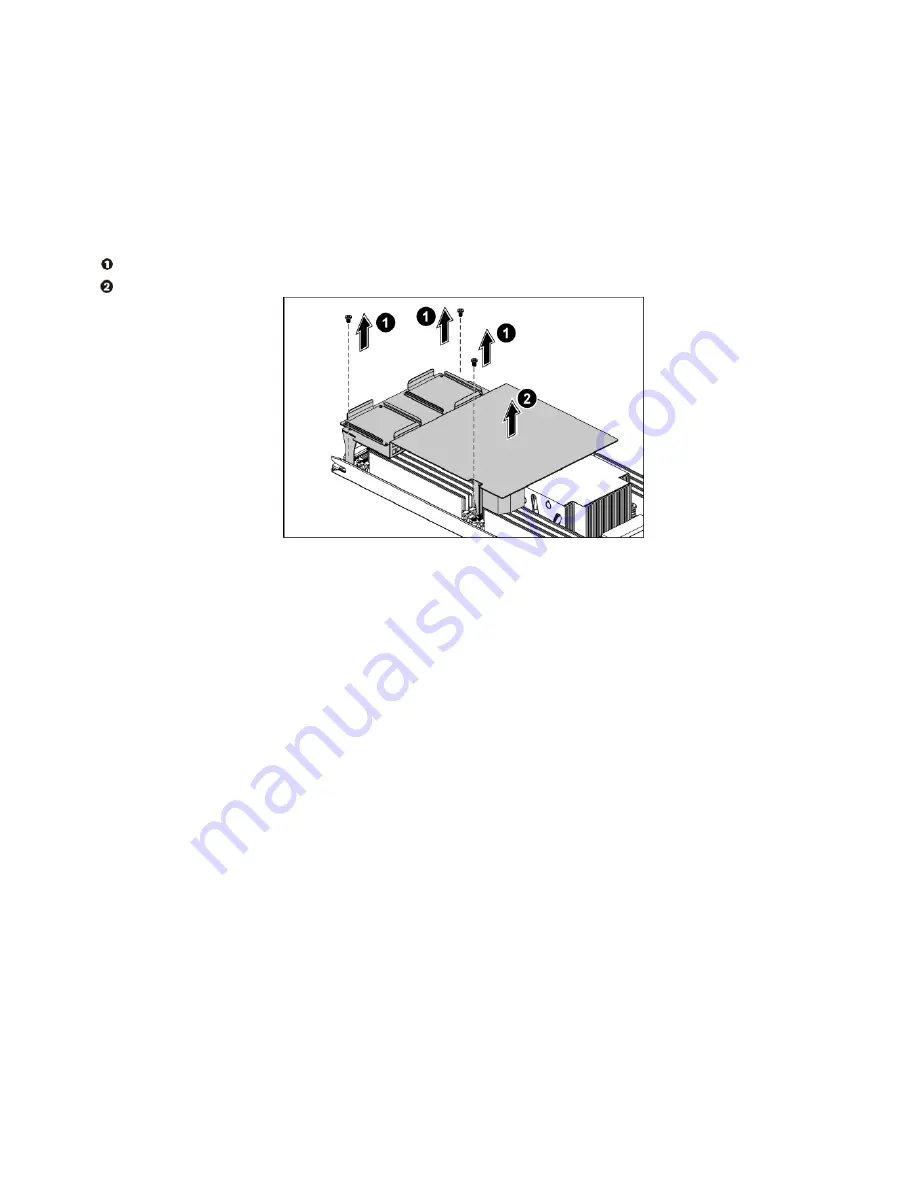
To remove the air duct


Before you remove the air duct, please turn off your node 


Loosen the screws that secure the fan duct. 

  Remove the air duct. 


                                                     Figure 2-22  Removing the Air Duct 


2.9.2 

To install the air duct


Reverse the steps above to install the air duct. 


2.10  System Fans


Subdividing the node area and the backplane area is a metal cage that holds the system fans. This CiB-
9224 V12 contains four system fans which are located inside the chassis.  These system  fans maintain 
the ideal temperature for the node, backplane and disk drives. 


The location of system fans is shown below: 


Содержание CiB-9224 V12

Страница 1: ...CiB 9224 V12 Tech Manual DataON Storage storage division of Area Data Systems Version Dec 2014 ...

Страница 2: ...ercountries Disclaimer This manual provides the information in relation to the set up and installation of the product herein Nothing herein may be construed as granting any right or license relating to any intellectual property rights of this manual or product Unless otherwise provided in the Purchase and Sale Agreement for this product manufacturer and distributor of this product will not be liab...

Страница 3: ...CiB 9224 V12 User Manual ...

Страница 4: ...art 19 2 2 Chassis Cover 19 2 2 1 To remove the chassis cover 19 2 2 2 To install the chassis cover 20 2 3 Power Supplies 21 2 3 1 To remove the power supply 21 2 3 2 To install the power supply 22 2 4 2 5 SAS HDDs 22 2 4 1 To remove a HDD 23 2 4 2 To install a HDD 24 2 5 Nodes 25 2 5 1 To remove the node 26 2 5 2 To install the node 26 2 6 SAS IO Module 26 2 6 1 To remove the JBOD board 27 2 7 Bo...

Страница 5: ...ols used throughout this manual Warning Information to prevent injury to yourself when trying to complete a task Caution Information to prevent damage to the components when trying to complete a task Important Information that you must follow to complete a task Note Tips and information to aid in completing a task ...

Страница 6: ...do not open this enclosure Indicates the presence of a hot surface or hot component Warning To reduce the risk of injury from a hot component allow the surface to cool before touching it Any RJ45 receptacle marked with this symbol indicates a network interface connection Warning To reduce the risk of electric shock fire or damage to the equipment do not plug telephone or telecommunications connect...

Страница 7: ...perly Electrical Safety Before installing or removing any components or cables ensure all power cords for system and attached devices are unplugged Antistatic wrist strap is recommended to prevent static discharge This product is equipped with three prong power cord and plug for user safety Make sure your electrical outlet is a properly grounded to avoid electric shock Nodes adapters and disk driv...

Страница 8: ...puncture shorten external contacts or dispose in fire or water Replace only with the spare parts designated for this product Batteries should not be littered along with the general household waste Please use the public collection system or return them to thesupplier Laser Peripherals or Devices Safety Toavoid risk of radiation exposure and or personal injury Do not open the enclosure of any laser ...

Страница 9: ...ypical office environment Such as Clean dry and free of airborne particles other than normal room dust Well ventilated and away from sources of heat including direct sunlight and radiators Vibration or physical shock free environment Provided with a properly grounded wall outlet ...

Страница 10: ... Information Technology Equipment UL 94 Tests for Flammability of Plastic Materials for Parts in Devices Appliances GB4943 Safety of Information Technology Equipment Product EMC Compliance This product has been tested and verified to comply with the following electromagnetic compatibility EMC regulations Communications Commission Notice Part 15 of the Federal Communications Commission FCC Rules an...

Страница 11: ...be required to correct the interference at personal expense Declaration of Conformity for Products Marked with the FCC Logo United States Only This device complies with Part 15 of the FCC Rules Operation and is subject to the following two conditions 1 this device may not cause harmful interference and 2 this device must accept any interference received including interference that may cause undesi...

Страница 12: ...vider Route power cords so that they will not be walked on or pinched by items placed upon or against them Pay particular attention to the plug electrical outlet and the point where the cords exit from the product Rack Mount Instructions The following or similar rack mount instructions are included with the installation instructions Elevated Operating Ambient If installed in a closed or multi unit...

Страница 13: ...ant PSU Dimension W x D x H 19 x 33 5 x 3 45 Weight 56lbs enclosure only Cluster Server Node Processor Intel Xeon E5 2600 V3 family Chipset Intel C612 Memory Slot 16 x DDR4 RDIMM up to 512GB Expansion Slot 3 x PCI e Gen 3 x8 2 Standard 1 Mezzanine Mezzanine Card Avago LSI 12G SAS HBA 3008 Network 2 x 10GbE SFP ports On board per node Management 1 x dedicated 10 100 RJ45 management port per node IP...

Страница 14: ...ut Figure 1 1 System Overview 1 Power Module 2 Nodes 3 Power Distribution Boards 4 Air Duct 5 Strong Plate 6 Middle Plane 7 Bridge Board 8 Front Panel 2 9 Front Panel 1 10 Drive Bays 11 2 5 HDD SSD Backplane 12 System Fans 13 Boot SSD 14 PCI e Expansion Card Cage Low Profile ...

Страница 15: ... HDD SSD configurations The 2U system allow front access to the HDD SSD In addition systems LEDs indicators is also located on the front for easy notification Figure 1 2 Front View of 24 x 2 5 drives 1 Front Panel 1 2 Drive Activity LED 3 Drive Status LED 4 HDDs SSDs 5 Front Panel 2 ...

Страница 16: ...Four Nodes 1 Power Supply 1 2 Power Supply 0 3 Rear Dual USB Port 4 10G NIC 0 Port 5 10G NIC 1 Port 6 Management Port 7 VGA Connector 8 Serial Port 9 ID LED 10 10G NIC 0 Link Activity LED 11 10G NIC 1 Link Activity LED 12 10G NIC 1 Speed LED 13 10G NIC 0 Speed LED 14 Power Button 15 HDMini SAS Connector 3 4 16 HDMini SAS Connector 1 2 17 SAS I O module Power LED ...

Страница 17: ...ns is located on the front panels of each side The LED indicator provides current system activities and serve as status of system power and ID of each node Figure 1 4 Front Panel Buttons and LEDs 1 ID Button for Node 1 2 Power Button for Node 1 3 ID Button for Node 2 4 Power Button for Node 2 ...

Страница 18: ...ve identifier SES Off Normal Red On Hard drive fail or port disable SES Off Normal Purple Blink Rebuild remap SES Blue Purple Blue Purple Blink Consistency check SES Front PanelLED Name Color Condition Function Status Power LED Green On Power on S0 S1 None Off Power off S4 S5 Amber Blink Warning Attention ID LED Blue On IPMI Via chassis identify command on or ID buttonpress ID on Off IPMI Via chas...

Страница 19: ...CiB 9224 V12 User Manual 15 1 3 5 Motherboard Connectors ...

Страница 20: ...er J27 12 PCI E x16 Slot J37 13 Password Clear Jumper J51 14 Card SGPIO Connector J71 15 DIMM Slots for Processor 0 C0 C1 D0 D1 16 DIMM Slots for Processor 1 A0 A1 B0 B1 17 Backplane Connectors J76 J77 18 Backplane Mini SAS Connector 0 J24 19 Backplane Mini SAS Connector 1 J23 20 Power Connector J64 21 DIMM Slots for Processor 1 C0 C1 D0 D1 22 Processor 1 CPU1 23 System Battery BH1 24 Processor 0 ...

Страница 21: ...el CPU 0 Channel A Channel B Channel C Channel D DIMM Slot A0 A1 B0 B1 C0 C1 D0 D1 2 CPU 8 DIMM V V V V 2 CPU 16 DIMM V V V V V V V V DIMM Channel CPU 1 Channel A Channel B Channel C Channel D DIMM Slot A0 A1 B0 B1 C0 C1 D0 D1 2 CPU 8 DIMM V V V V 2 CPU 16 DIMM V V V V V V V V ...

Страница 22: ...CiB 9224 V12 User Manual 18 1 3 7 Block Diagram ...

Страница 23: ... systems does not means is fully power off Internal circuitry may remain Active Disconnect all power cords from the system to completely power off the system 2 2 Chassis Cover The system is a 2U form factor Designed for components maintenance ease Reminder Before you remove or install the chassis cover please follow the step below Step 1 Make sure the system is off and disconnected from a power so...

Страница 24: ...he chassis cover to the right position on the chassis as shown below and then slide it to the front until it is closed Secure the chassis cover with one screw Figure2 3 Tightening the Screw To ensure proper cooling Chassis cover must be install before turning on the system ...

Страница 25: ...stem is shown below Figure2 4 Power Supply Locations Please follow the steps below before removing or installing the power supply modules Step 1 Disconnect all necessary cables 2 3 1 To remove the powersupply Pull up thehandle Press the retaining clip on the right side of the power supply along the direction of the arrow At the same time pull out the power supply The power supply takes considerabl...

Страница 26: ...Installing the PowerSupply 2 4 2 5 SAS HDD SSD The CiB 9224 V12 support up to 24 x 2 5 hot pluggable SAS HDD SSD You don t need to power off the system when removing or installing a HDD SSD The location of 2 5 SAS HDD SSD assemblies on the system is shown below Figure 2 7 2 5 SAS HDD SSD Locations Take note of the drive tray orientation before sliding it out Tray will not fit back into the bay if ...

Страница 27: ...SSD Push the release button Pull the lever open Slide the HDD SSD assembly out of the Drive bay Figure2 8 sliding out the HDD Assembly Loosen the four screws that secure the HDD SSD Lift the HDD SSD out of the Drive tray Figure2 9 Removing the HDD SSD ...

Страница 28: ... User Manual 24 2 4 2 To install a HDD SSD Place the HDD SSD to the Drive tray Figure 2 10 Placing the HDD SSD to the Drive Tray Secure the HDD SSD to the Drive tray with four screws Figure2 11 Fastening the Screws ...

Страница 29: ...2 Installing the Drive Bay Make sure that the HDD SSD is connected to the Drive connector on the backplane 2 5 Nodes CiB 9224 V12 system supports two nodes The location of node on the system is shown below Figure2 13 Node Locations Reminder Before you remove or install the node please follow the steps below Step 1 Make sure the Node is turned off Step 2 Disconnect all necessary cables ...

Страница 30: ...the chassis by using the handle Figure2 14 Removing the Node 2 5 2 To install the node Push the node into the chassis until it s completely seated in place Secure thescrew Figure2 15 Installing the Node 2 6 SAS I O Module The CiB 9224 V12 supports two SAS I O modules The location of module on the system is show below ...

Страница 31: ...O module at a time Make sure at least on SAS I O module to provide I O path to HDD SSD Step 2 Disconnect all necessary cables 2 6 1 To remove the SAS I O module Pull the leveropen Slide the SAS I O module out of the chassis by using the lever Figure2 17 Removing the SAS I O module When install the SAS I O module Please mind fingers between the lock hinge and tray as it may cost injuries ...

Страница 32: ...e SSD out of the SSD tray along the direction of the arrow Figure 2 19 Removing the SSD 2 8 X16 Riser PCI e Card 2 8 1 To remove the expansion card cage Reminder Before you remove or install the PCI e Expansion Card please follow the steps below Step 1 Make sure the server is turned off and disconnected to any AC power source ...

Страница 33: ...he node Figure 2 20 Removing the Expansion Card Cage 2 8 2 To remove the expansion Card Loosen the screws that secure the expansion card Remove the expansion card Install the expansion card slot cover Figure2 21 Removing the ExpansionCard 2 8 3 To install the expansion card Reverse the steps above to install the expansion card ...

Страница 34: ...the Air Duct 2 9 2 To install the air duct Reverse the steps above to install the air duct 2 10 System Fans Subdividing the node area and the backplane area is a metal cage that holds the system fans This CiB 9224 V12 contains four system fans which are located inside the chassis These system fans maintain the ideal temperature for the node backplane and disk drives The location of system fans is ...

Страница 35: ...o the AC power Step 2 Remove the chassis cover and strong plate To remove the chassis cover see 2 2 Chassis Step 3 Disconnect all the necessarycables 2 10 1 To remove a system fan Lift a system fan out of the chassis directly Figure 2 24 Removing a System Fan 2 10 2 To install a system fan Reverse the step above to install a system fan Figure2 23 Removing the Air Duct ...

Страница 36: ...I Appendix China RoHS Regulations Figure I China RoHSRegulations ...

Отзывы: