94
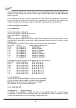
Items, which are valid for the current device but aren't supported by current programmer, are
disabled. These settings are saving to disk along with associated device by
File / Exit and
save
command.
The commonly used term are also explained in the user manual to programmer. The special
terms used here are exactly the terms used by manufacturer of respective chip. Please read
the documentation to the chip you want to program for explanation of all used terms.
List of commonly used items:
group
Addresses
:
device start address (default 0)
device end address (default device size-1)
buffer start address (default 0)
Split
(default none)
This option allows setting special mode of buffer when programming or reading device. Using
split options is particularly useful when using 8-bit data memory devices in 16-bit or 32-bit
applications.
Following table describes buffer to device and device to buffer data transfer
Split
type Device
Buffer Address assignment
None
Device[ADDR]
Buffer[ADDR]
Even
Device[ADDR]
Buffer[2*ADDR]
Odd
Device[ADDR]
Buffer[1+(2*ADDR)]
1./4
Device[ADDR]
Buffer[4*ADDR]
2./4
Device[ADDR]
Buffer[1+(4*ADDR)]
3./4
Device[ADDR]
Buffer[2+(4*ADDR)]
4./4
Device[ADDR]
Buffer[3+(4*ADDR)]
Real addressing will be following: (all addresses are hexadecimal)
Split
type Device
addresses
Buffer addresses
None
00 01 02 03 04 05
00 01 02 03 04 05
Even
00 01 02 03 04 05
00 02 04 06 08 0A
Odd
00 01 02 03 04 05
01 03 05 07 09 0B
1./4
00 01 02 03 04 05
00 04 08 0C 10 14
2./4
00 01 02 03 04 05
01 05 09 0D 11 15
3./4
00 01 02 03 04 05
02 06 0A 0E 12 16
4./4
00 01 02 03 04 05
03 07 0B 0F 13 17
Terms explanation:
Access to device address ADDR is written as Device[ADDR].
Access to buffer address ADDR is written as Buffer[ADDR].
ADDR value can be from zero to device size (in bytes).
All addresses are byte oriented addresses.
group
Insertion test:
insertion test
(default ENABLE)
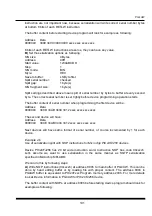
If enabled, the programmer checks all pins of the programmed chip, if have proper
connection to the ZIF socket (continuity test). The programmer is able to identify the wrong
contact, misinserted chip and also (partially) backinserted chip.
Содержание Dataman-40Pro
Страница 7: ...Quick Start 7 Introduction ...
Страница 12: ...12 Quick Start ...
Страница 14: ...14 4 check if the device is blank click on 5 program device click on 6 additional verify of device click on ...
Страница 15: ...Detailed description 15 Detailed description ...
Страница 16: ...16 DATAMAN 448PRO2 ...
Страница 30: ...30 DATAMAN 48PRO2 DATAMAN 48PRO2C ...
Страница 45: ...DATAMAN 40PRO 45 DATAMAN 40PRO ...
Страница 54: ...54 DATAMAN MEMPRO ...
Страница 61: ...Setup 61 Setup ...
Страница 65: ...Setup 65 Step 6 Check your setting and then click on Install button Step 7 Installation process will start ...
Страница 70: ...70 Step 6 Click on Continue Anyway button For Windows Vista Click Install this driver software anyway ...
Страница 72: ...72 PG4UW ...
Страница 141: ...PG4UWMC 141 PG4UWMC ...
Страница 154: ...154 Installation procedure customized ...
Страница 159: ...Common notes 159 Common notes ...
Страница 171: ...Troubleshooting and warranty 171 Troubleshooting and warranty ...

