


INTRODUCTION
35
2
Test Mode (Function 1)
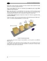
Once entered, the Bar Graph on the five LEDs is activated and if the imager starts reading
codes the Bar-Graph shows the Good Read Rate. In case of a NO READ condition, only the
Status
LED is on and blinks.
The Bar Graph has the following meaning:
To exit the Test Mode, press the X-
PRESS™ push button once.
NOTE:
By default, the Test exits automatically after three minutes.
Aim/Autofocus (Function 2)
This function causes the laser pointers to turn on. Since the laser pointers are centered on
the FOV they can be used to position the imager on the code. The Aim LED blinks to indicate
this state. After a short delay, this function also performs the Autofocus procedure for Liquid
Lens models.
You can exit the Aim/Autofocus function at any time by pressing the X-
PRESS™ push button
once. After a short delay the autofocus procedure is cancelled and the laser pointers turn off.
Setup (Function 3)
Once entered, the imager automatically performs Image Acquisition parameter calibration for
the specific code presented to it.
The Setup LED will blink until the procedure is completed.
The Setup procedure ends when the Image Acquisition parameters are successfully saved in
the reader memory, the Setup LED will stop blinking
and Matrix 300™ emits 3 high pitched
beeps.
If the calibration cannot be reached after a timeout of about 5 (five) se
conds Matrix 300™ will
exit without saving the parameters to memory, the Setup LED will stop blinking and in this case
Matrix 300™ emits a long low pitched beep.
≥
95
%
≥
20
%
≥
40
%
≥
60
%
≥
75
%
Содержание Matrix 300
Страница 1: ...REFERENCE MANUAL Matrix 300...
Страница 68: ...MATRIX 300 REFERENCE MANUAL 56 4 Figure 41 ID NET Network Connections with isolated power blocks...
Страница 69: ...CBX ELECTRICAL CONNECTIONS 57 4 Figure 42 ID NET Network Connections with Common Power Branch Network...
Страница 70: ...MATRIX 300 REFERENCE MANUAL 58 4 Figure 43 ID NET Network Connections with Common Power Star Network...
Страница 118: ...MATRIX 300 REFERENCE MANUAL 106 7 Figure 78 Options Communication Serial Port Figure 79 Options Communication Ethernet...
Страница 160: ......