


TYPICAL LAYOUTS
75
5
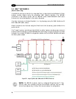
5.4 BUILT-IN PROFINET-IO NETWORKS
The PROFINET-IO interface is used to collect data from several readers to build a multi-point
or a multi-sided reading system; there can be one PROFINET-IO Controller (Host) and up to
255 PROFINET-IO Devices (Scanners) connected together in the same subnetwork.
Before proceeding with the connection, it is necessary to configure the scanner. This can be
done via Genius through the Ethernet socket. For further details see par. 2.10. Once a
connection is established, the scanner can also be configured by sending Host Mode
programming strings from the PLC, see the 5K Host Mode Programming Manuals.
5.4.1 Multi Station Layout with Single Port Scanners
(x3xx models)
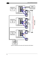
One or more DS5100-x3xx model scanners can be connected to the network by using
CAB-
ETH-M0x
cables connected to a Certified PROFINET-IO Switch or PLC. Every scanner must
have its own unique Station Name (see Profinet-IO Line Parameters in Help On Line).
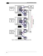
For a Multi Station layout each scanner independently receives the Trigger signal (Trigger
Input from presence sensor, Input from Fieldbus Host, or Serial Start/Stop from Fieldbus
Host) and each scanner sends its message to the Host.
In the example below, Power and an External Trigger are brought to each scanner through a
CBX connection box using the
CAB-DS0x-S
cables.
Figure 56
– PROFINET-IO Multi Station Layout (Single Port Models)
PROFINET-IO Interface
External Trigger (for On Line Mode)
CBX
Scanner
HOST
Certified
PROFINET-IO
Switch
Power
CAB
-ETH
-M0
x
CAB
-DS
xx
-S
Scanner
Scanner
1
2
CAB-ETH-M0x
CAB-ETH-M0x
Содержание DS5100-X200
Страница 1: ......
Страница 29: ...RAPID CONFIGURATION 13 1 b Operating mode selection and definition a Digital Inputs configuration ...
Страница 30: ...DS5100 REFERENCE MANUAL 14 1 b Digital Outputs configuration c Hardware interface selection ...
Страница 62: ...DS5100 REFERENCE MANUAL 46 3 Figure 18 DS5100 OM Serial Model Overall Dimensions ...
Страница 78: ...DS5100 REFERENCE MANUAL 62 4 Figure 38 ID NET Network Connections with isolated power blocks ...
Страница 79: ...ELECTRICAL INSTALLATION 63 4 Figure 39 ID NET Network Connections with Common Power Branch Network ...
Страница 80: ...DS5100 REFERENCE MANUAL 64 4 Figure 40 ID NET Network Connections with Common Power Star Network ...
Страница 97: ...TYPICAL LAYOUTS 81 5 7 Double click on the DS5100 scanner to configure it ...
Страница 163: ...147 X X PRESS Human Machine Interface 23 ...
Страница 164: ......


