


ELECTRICAL INSTALLATION
61
4
4.3.2 ID-NET Response Time
The following figure shows the response time of the ID-NET network. This time is defined as
the period between the Trigger activation and the beginning of data transmission to the Host.
Max ID-NET Response Time
240
220
200
180
160
140
120
100
80
60
40
20
0
R
es
pons
e Tim
e (m
s)
Number of Nodes
500 kbps
250 kbps
125 kbps
0
1
2
3
4
5
6
7
8
9
10 11
12 13 14 15 16
Figure 37
– ID-NET Response Time
CONDITIONS:
ID-NET Synchronized layout
message length = 50 bytes per node
Содержание DS5100-X200
Страница 1: ......
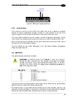
Страница 29: ...RAPID CONFIGURATION 13 1 b Operating mode selection and definition a Digital Inputs configuration ...
Страница 30: ...DS5100 REFERENCE MANUAL 14 1 b Digital Outputs configuration c Hardware interface selection ...
Страница 62: ...DS5100 REFERENCE MANUAL 46 3 Figure 18 DS5100 OM Serial Model Overall Dimensions ...
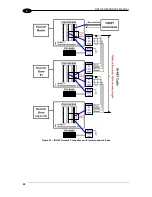
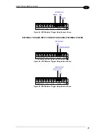
Страница 78: ...DS5100 REFERENCE MANUAL 62 4 Figure 38 ID NET Network Connections with isolated power blocks ...
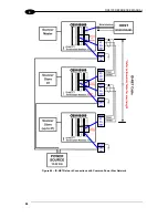
Страница 79: ...ELECTRICAL INSTALLATION 63 4 Figure 39 ID NET Network Connections with Common Power Branch Network ...
Страница 80: ...DS5100 REFERENCE MANUAL 64 4 Figure 40 ID NET Network Connections with Common Power Star Network ...
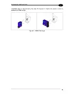
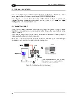
Страница 97: ...TYPICAL LAYOUTS 81 5 7 Double click on the DS5100 scanner to configure it ...
Страница 163: ...147 X X PRESS Human Machine Interface 23 ...
Страница 164: ......


